Install guide for adding a Dual Frequency Oscillator (DFO) to a Sony PlayStation. The dual frequency oscillator will allow a region modified console to have a correct video clock frequency relative to the video refresh rate, rather than an out of spec one when using a forced video refresh rate. They make PAL/50Hz consoles comparable to real NTSC/60Hz consoles. In PU-8 and PU-18 consoles the DFO will also allow the console to create the correct subcarrier frequency for colour over composite, RF and S-video.
General DFO Install Steps
1. Remove Original Clock Source
The original clock will need isolating from GPU Pin 192, which is the clock input pin. This is done by removing the 220ohm resistor between the original Crystal/Oscillator and GPU Pin 192.
2. Connect New Clock Source from DFO
The Dual Frequency Oscillator clock will need feeding to GPU Pin 192 to replace what would have been fed from the original Crystal/Oscillator. DFO CLK OUT to GPU Pin 192.
Some DFO boards will need a 220ohm resistor soldering between DFO CLK OUT and GPU Pin 192, these boards have an 18ohm resistor at the CLK OUT pad. If the DFO board already has a 220ohm resistor at the CLK OUT pad replacing the 18ohm resistor, then no additional resistor is needed between DFO CLK OUT PAD and GPU PIN 192.
3. Connect a PAL/NTSC Switch to the DFO SO Pad
Sony PlayStation consoles change the video rate of the console based on the region of the game being run. North American and Japanese games force the console into 60Hz. European games force the console into 50Hz. The Dual Frequency Oscillator needs to change its clock frequency based on the region of game being run. This is done by connecting the PAL/NTSC switching pin of the GPU to the S0 pad of the DFO. GPU Pin 157 to DFO S0.
4. Power the DFO
The DFO will need connecting to ground and a 3.3V source to work.
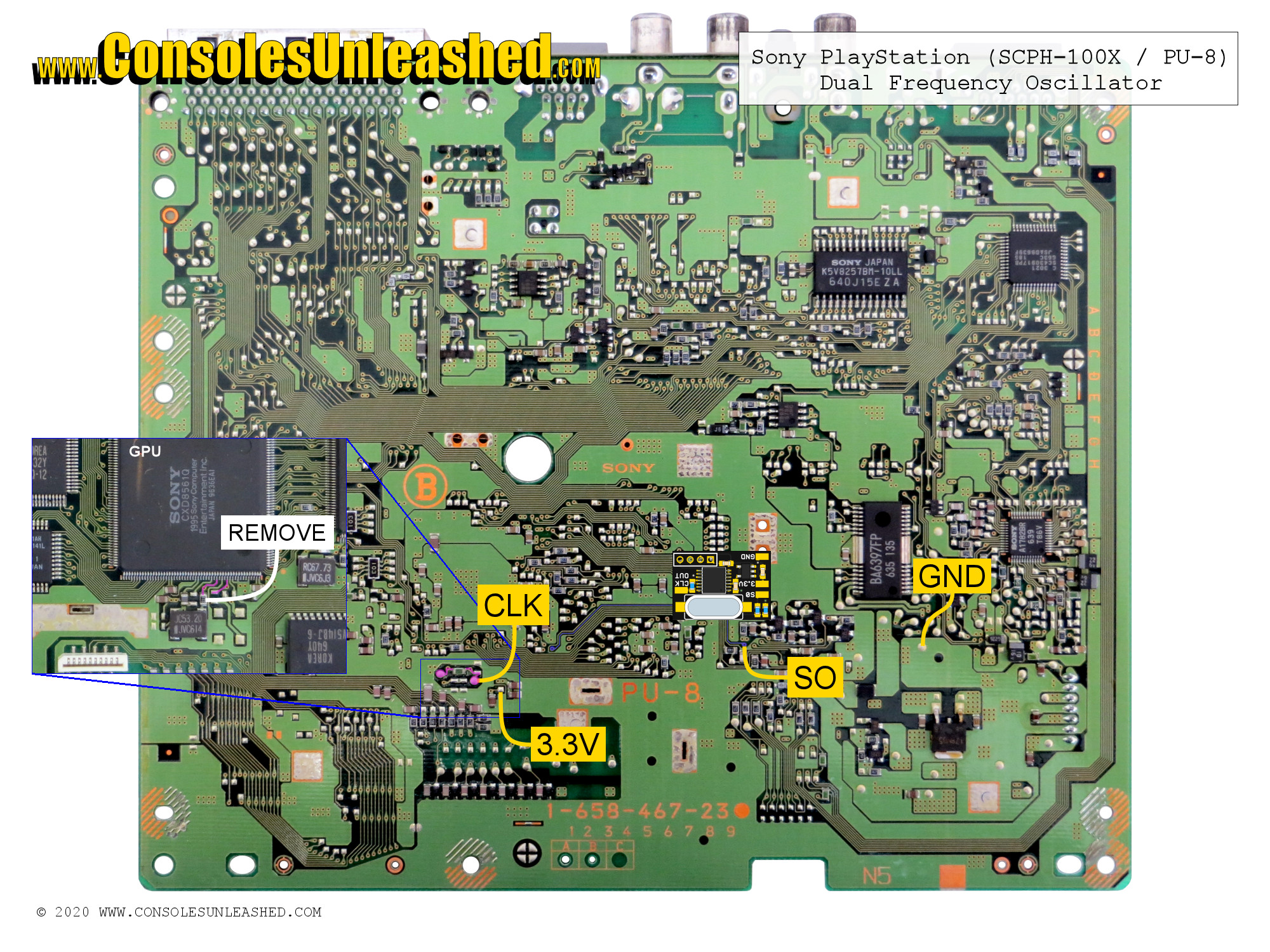
PlayStation SCPH-100X PU-8 DFO Install
This is an underside install location.
- Remove the 220ohm resistor connecting
IC204Pin 1 to GPU Pin 192. This will completely isolate the clock from the GPU ready for the DFO clock to be used instead. - Connect DFO S0 pad to a point that connects to GPU Pin 157. This pin will change from Ground and 3.3V depending on the region of the game being run. This is used to switch the DFO’s frequency.
- Connect DFO CLK OUT pad to a location that connects to GPU Pin 192.
GPU Pin 192 is the clock input for PAL consoles.
Board Revision: PU-8 / 1-658-467-12
Coming soon.
Board Revision: PU-8 / 1-658-467-23
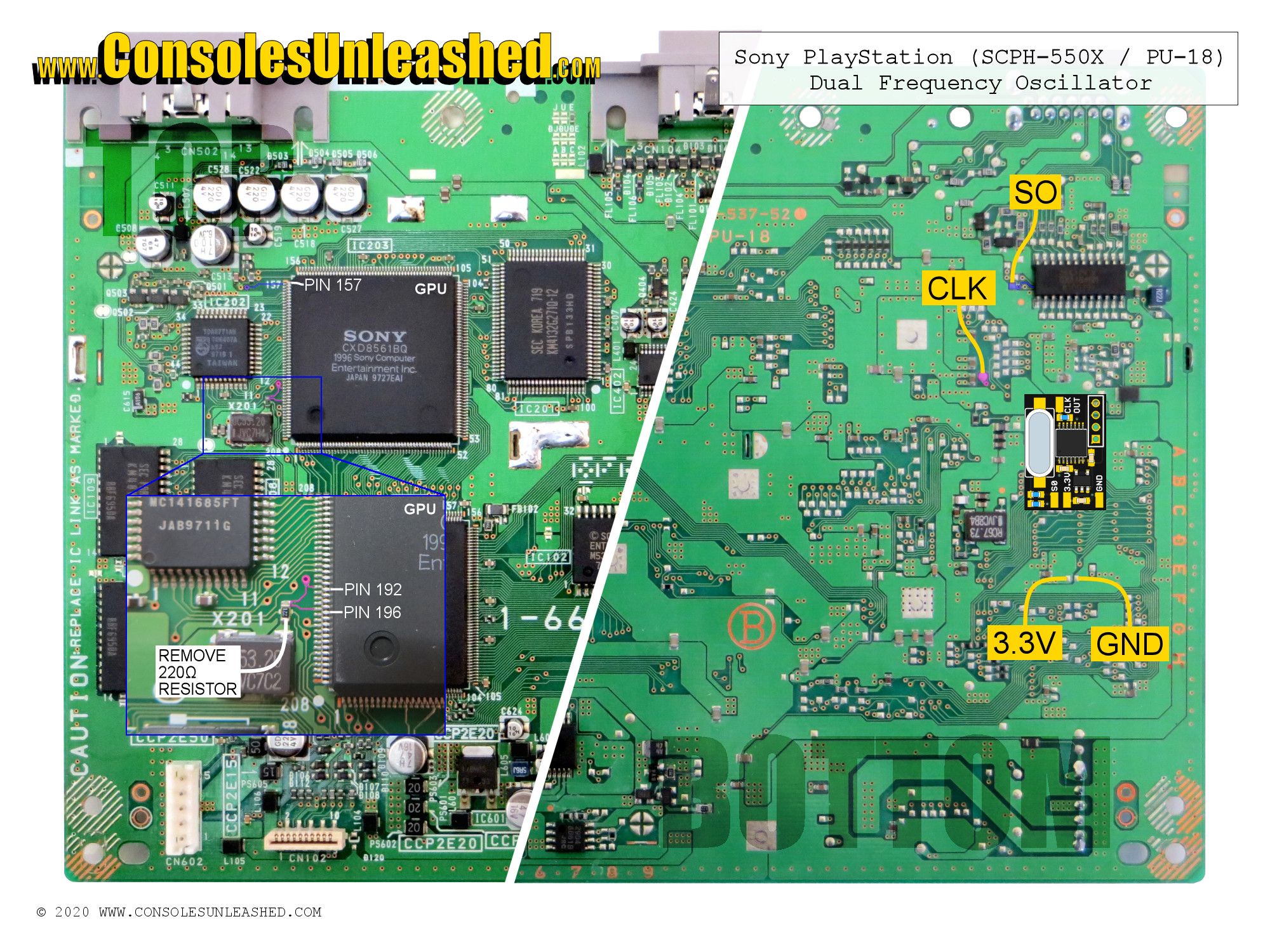
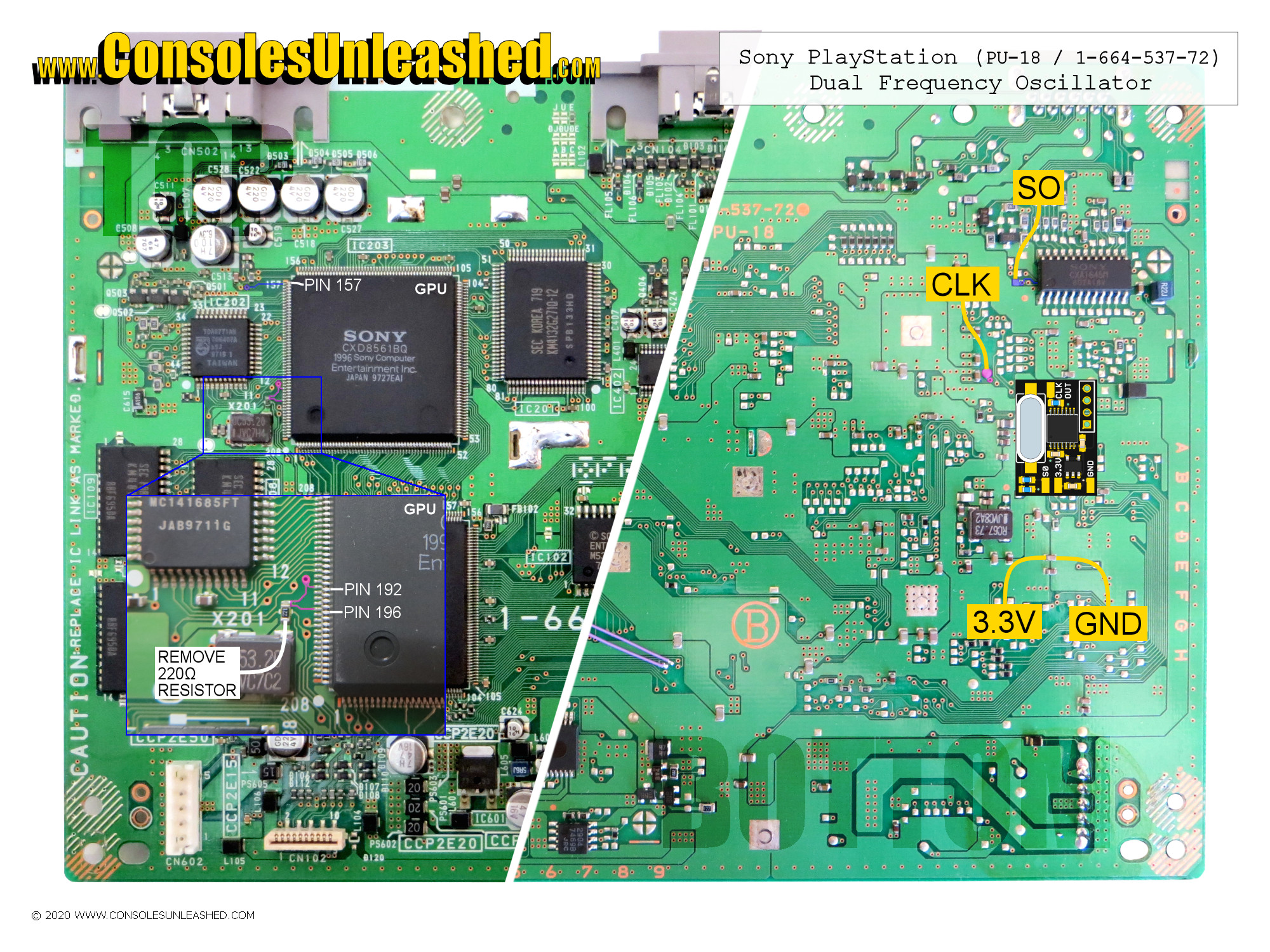
PlayStation SCPH-550X PU-18 DFO Install
This is an underside install location.
- Remove the RF shield located on the top of the console by desoldering the six solder connections. It is possible to leave the central and largest solder connection connected and bend the RF shield back to access the clock resistor. This might be a good option for some.
- Remove the 220ohm resistor connecting X201 to GPU Pin 192. This will completely isolate the clock from the GPU ready for the DFO clock to be used instead.
- Connect DFO S0 pad to a point that connects to GPU Pin 157. This pin will change from Ground and 3.3V depending on the region of the game being run. This is used to switch the DFO’s frequency .
- Connect DFO CLK OUT pad to a location that connects to GPU Pin 192.
Board Revision: PU-18 / 1-664-537-52 (*-11/*-21/*-62)
Board Revision: PU-18 / 1-664-537-72
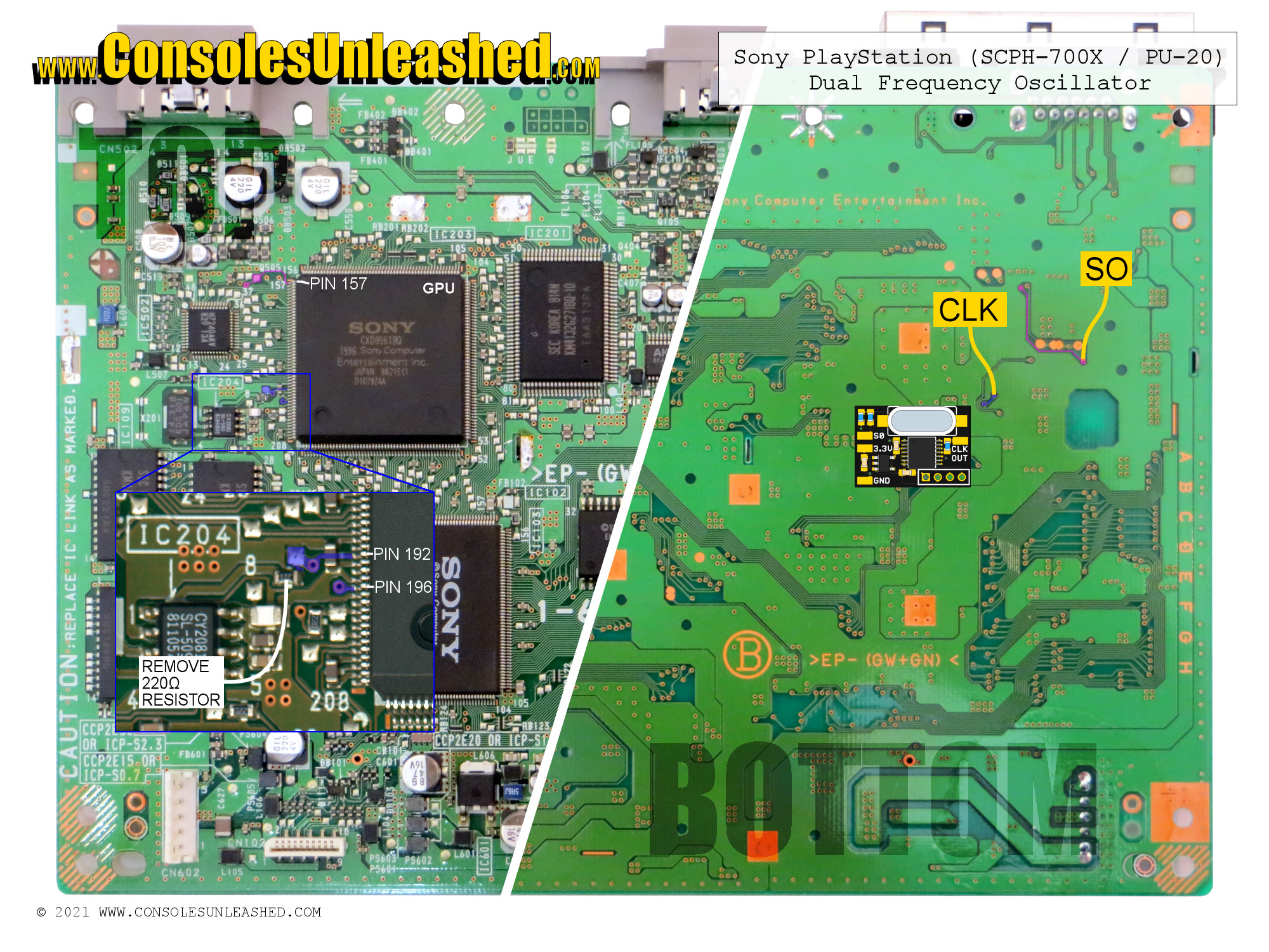
PlayStation SCPH-700X PU-20 DFO Install
This is an underside install location.
- Remove the RF shield located on the top of the console by desoldering the six solder connections. It is possible to leave the central and largest solder connection connected and bend the RF shield back to access the clock resistor. This might be a good option for some.
- Remove the 220ohm resistor connecting IC204 Pin 1 to GPU Pin 192. This will completely isolate the clock from the GPU ready for the DFO clock to be used instead.
- Connect DFO S0 pad to a point that connects to GPU Pin 157. This pin will change from Ground and 3.3V depending on the region of the game being run. This is used to switch the DFO’s frequency .
- Connect DFO CLK OUT pad to a location that connects to GPU Pin 192.
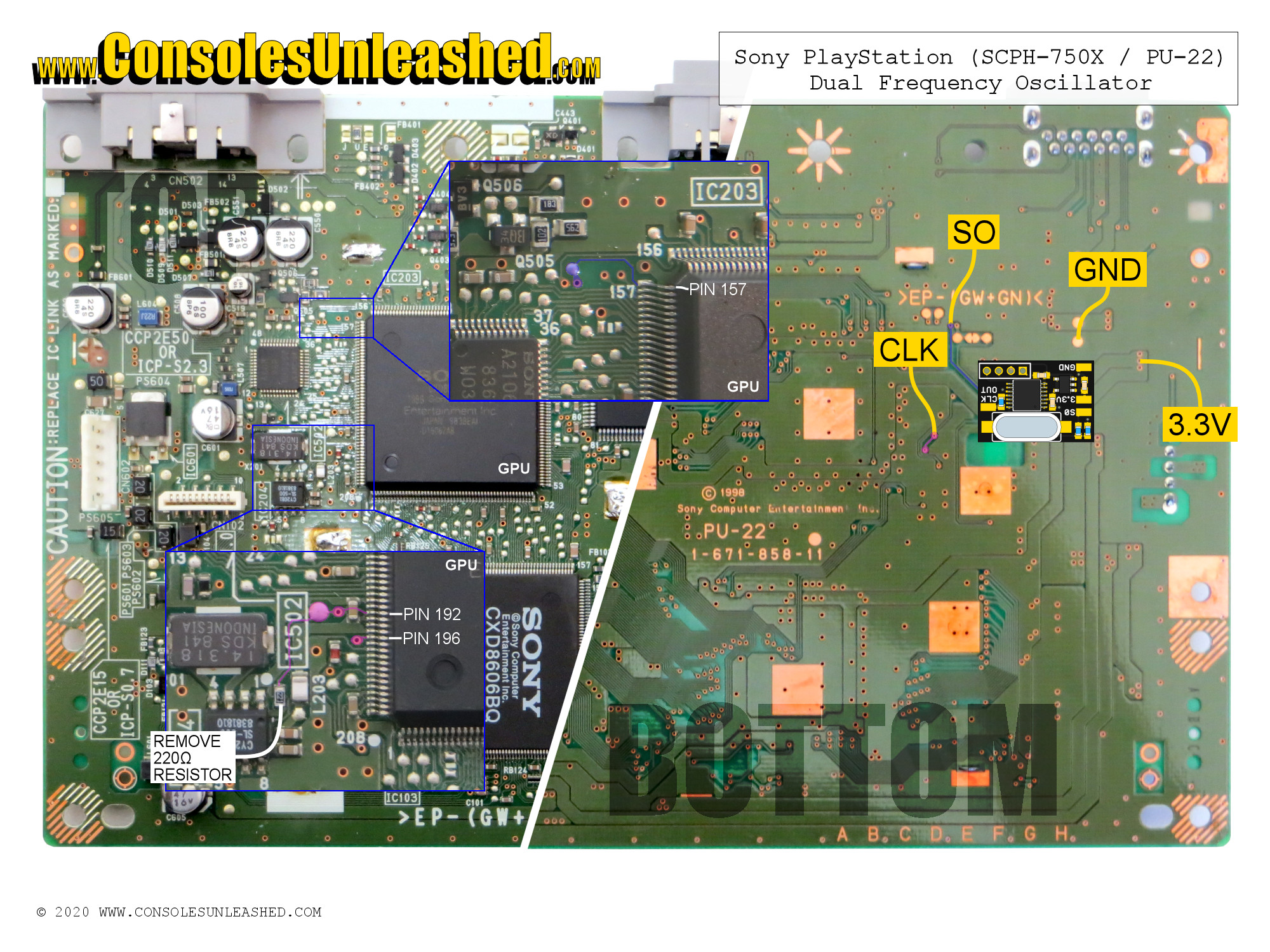
PlayStation SCPH-750X PU-22 DFO Install
This is an underside install location.
- Remove the 220ohm resistor connecting IC204 Pin 1 to GPU Pin 192. This will completely isolate the clock from the GPU ready for the DFO clock to be used instead.
- Connect DFO S0 pad to a point that connects to GPU Pin 157. This pin will change from Ground and 3.3V depending on the region of the game being run. This is used to switch the DFO’s frequency .
- Connect DFO CLK OUT pad to a location that connects to GPU Pin 192.
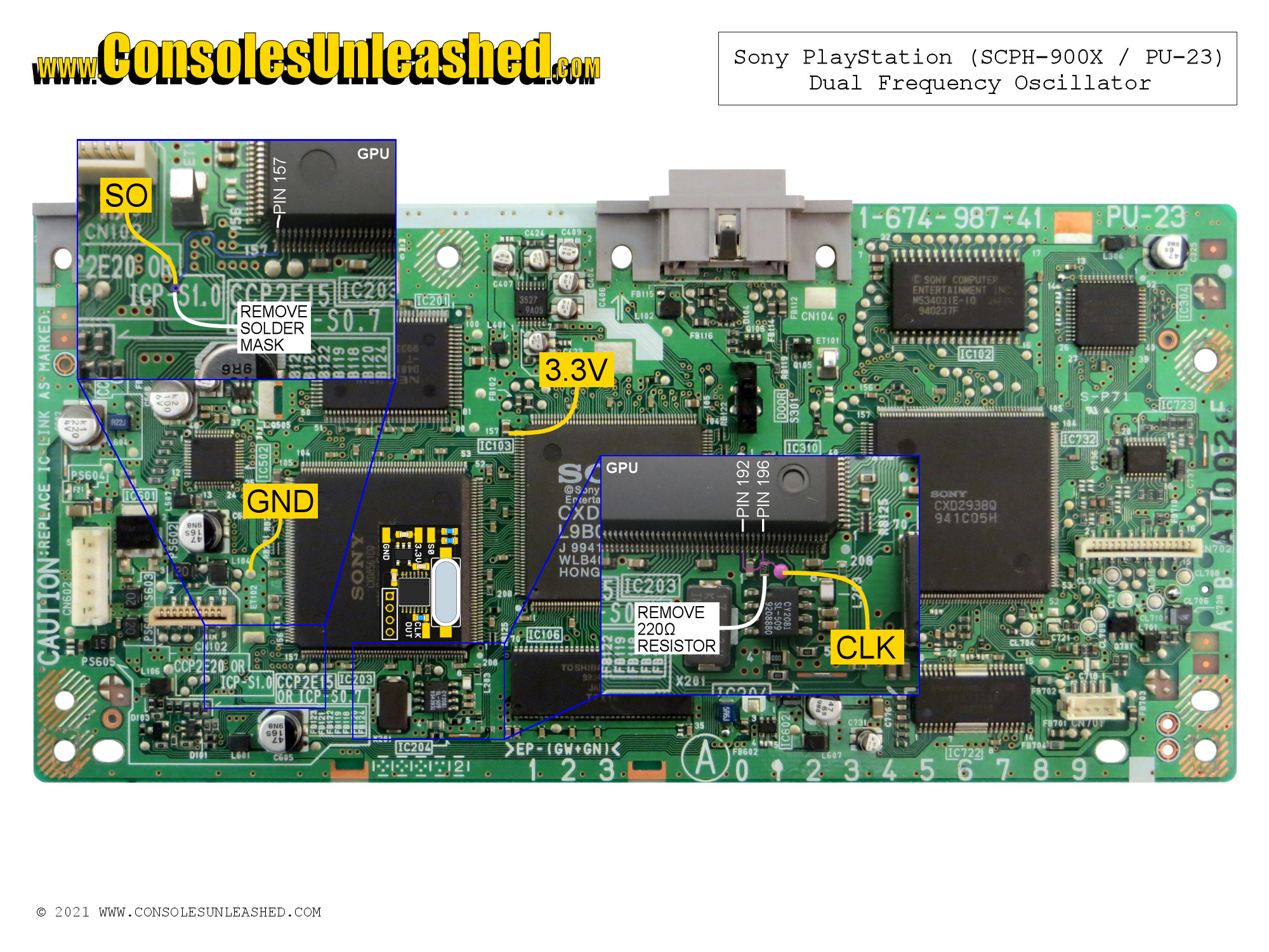
PlayStation SCPH-900X PU-23 DFO Install
This is a top install location.
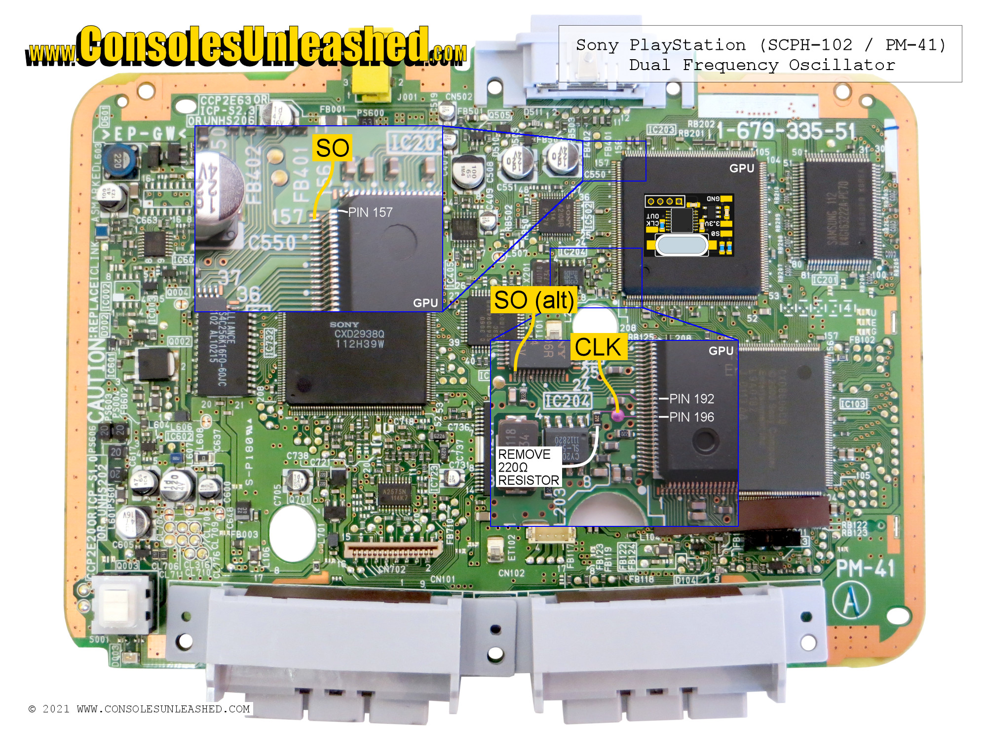
PlayStation SCPH-10X PM-41 DFO Install
This is a top install location.
Notes
The install guides here have not been ratified with colour over composite and RF video mods but they will be at some point. The ideal is to have correct clock frequencies and full colour at all outputs for all regions. Not applicable for PU-8 and PU-18 which create the correct subcarrier frequencies with a DFO.
PU-8 consoles can have a second crystal installed which will make the use of a DFO redundant. However crystals at the correct clock frequencies are becoming scarce which is possibly a good argument for using a DFO.