Solder Map
How it Works
There are 4 banks on the chip that is used for the MultiBIOS. Each of these banks can contain a separate BIOS file. The chip selects which bank to use based on what signal it received on pins 38 and 39.
AT27C4096
| Pin 38 | Pin 39 | |
| 128K Bank 1 | Ground | Ground |
| 128K Bank 2 | +5v | Ground |
| 128K Bank 3 | Ground | +5v |
| 128K Bank 4 | +5v | +5v |
These signals can be sent from the chip used for the Mega Drive switchless mod. These signals are routed to unused pins on the Mega Drive expansion port. The corresponding expansion port pins on the Mega CD are then routed to the pins on the MultiBIOS chip.
That’s the basic summary of what is happening. The below tables show how the signals work together.
AT27C4096 Bank Select
| Bank | Pin 38 | Pin 39 |
| 128K Bank 1 | Ground | Ground |
| 128K Bank 2 | +5v | Ground |
| 128K Bank 3 | Ground | +5v |
| 128K Bank 4 | +5v | +5v |
Mega Drive Region Settings
| Region | Video Rate | Language |
| Nothing | ||
| 60Hz/jp (Japan) | +5v | Ground |
| 50Hz/en (Europe) | Ground | +5v |
| 60Hz/en (North America) | +5v | +5v |
MultiBIOS with Universal BIOS Order
| AT27C4096 Bank | BIOS Order | Pin 38 | Pin 39 |
| 128K Bank 1 | North America | Ground | Ground |
| 128K Bank 2 | Japan | +5v | Ground |
| 128K Bank 3 | Europe | Ground | +5v |
| 128K Bank 4 | North American | +5v | +5v |
Modding the Mega Drive
Two wires need routing from the switchless chip to the expansion port on the Mega Drive. These signals will control the Bank Select of the MultiBIOS.
Pay close attention to the pins that need connecting to the MultiBIOS. The switchless mods with inverted outputs have reversed bank select wires when compared to switchless mods without inverted outputs.
Universal order MultiBIOS is named such because it will work with both standard and inverted video and language outputs. It just requires swapping the wires going from the switchless chip to the MultiBIOS which will reverse Bank 2 and Bank 3 of the MultiBIOS.
Switchless Mod Type
Your Mega Drive may have one of the following switchless mod chips installed. Each one requires different pins routing to the MultiBIOS.
D’force3000
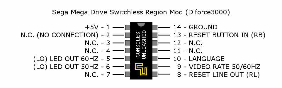
- Pin 10 = Language (to MultiBIOS Pin 39)
- Pin 9 = Video Rate (to MultiBIOS Pin 38)
Borti4938
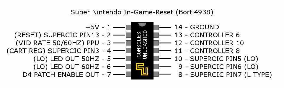
- Pin 10 = Inverted Language (to MultiBIOS Pin 38)
- Pin 8 = Inverted Video Rate (to MultiBIOS Pin 39)
Seb
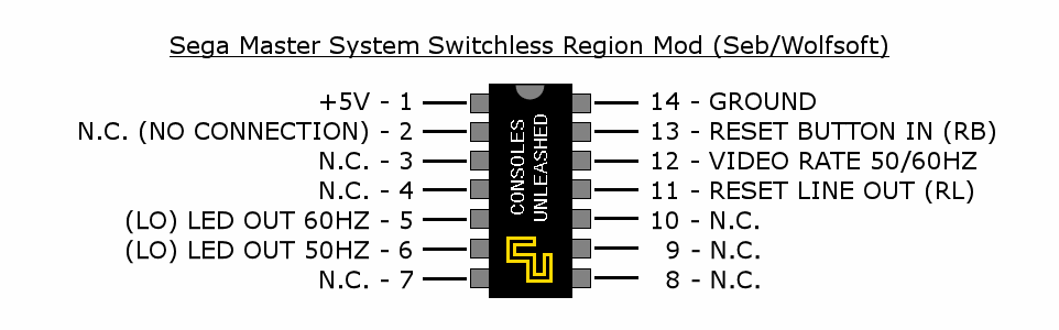
- Pin 10 = Inverted Video Rate (to MultiBIOS Pin 39)
- Pin 8 = Inverted Language (to MultiBIOS Pin 38)
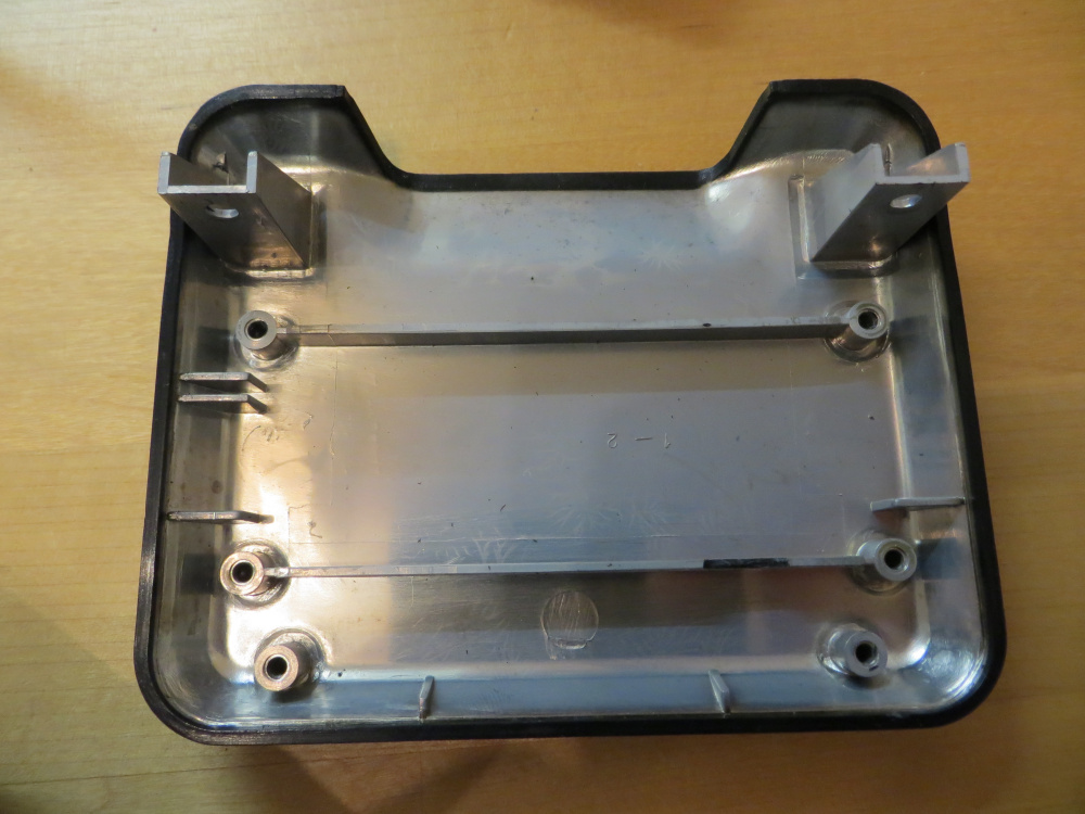
It’s important to mask off the area with Kapton tape before tinning and soldering. Cheap Kapton tape is fine.
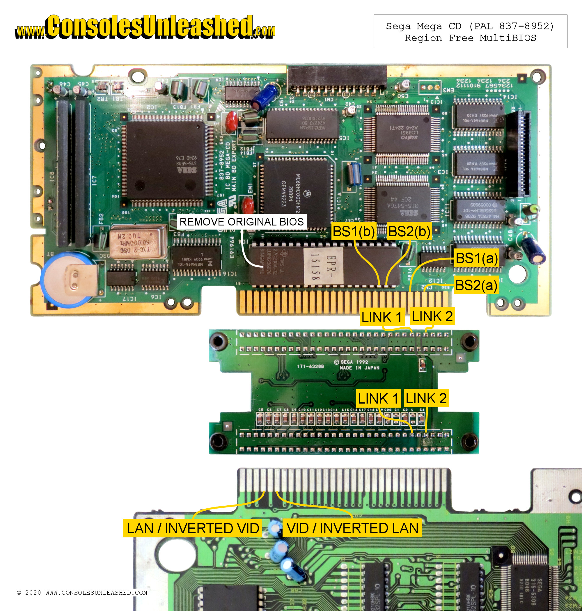
Modding the Mega CD
You will need to remove the original Mega CD BIOS chip and install a socket in its place. This will be covered in a separate guide.
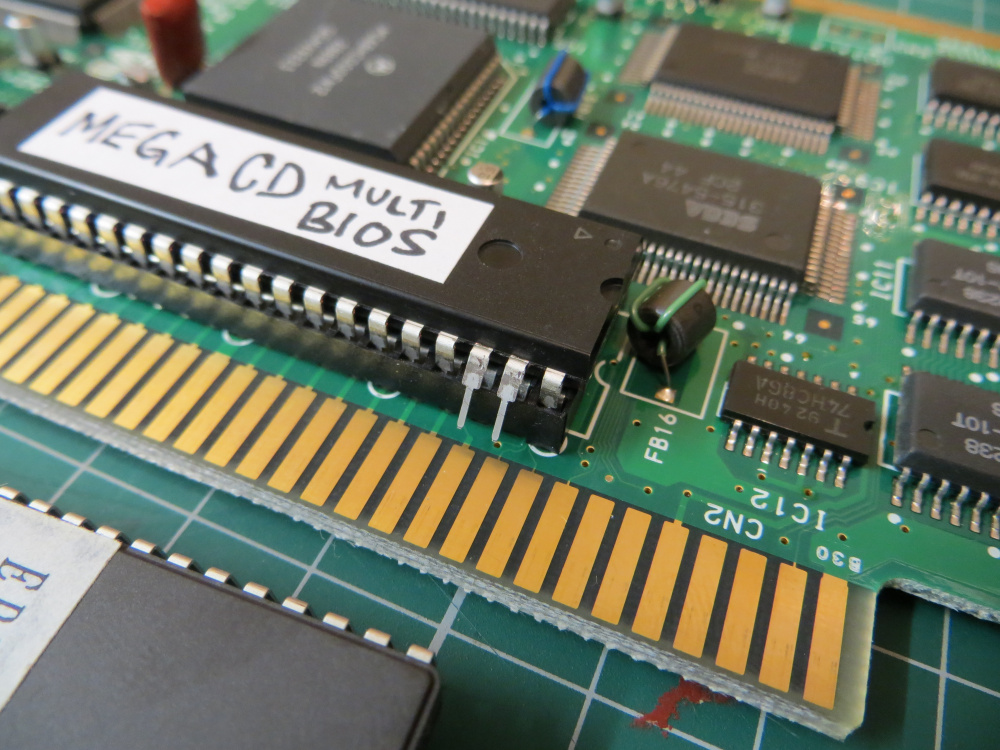
When installing the MulitBIOS into the socket you will be leaving Pins 38 and 39 out of the socket.
First make sure the pins of the chip align with the socket by placing it on top. Do not push it in.
If the pins do not align, you will have to bend the pins inwards. You can do this on a flat, hard surface. Place chip sideways onto the surface and use the surface to bend one side of the pins inwards. Repeat for the opposite row of pins. Do this gently and check if they align with the socket each time.
When the two rows of pins align with the socket you can bend pins 38 and 39 outwards. (Remember chip pins are counted anticlockwise starting from the left. A small circle indicates Pin 1 or a half circle cut indicates which side of the chip to start counting from.
Push the chip into the socket.
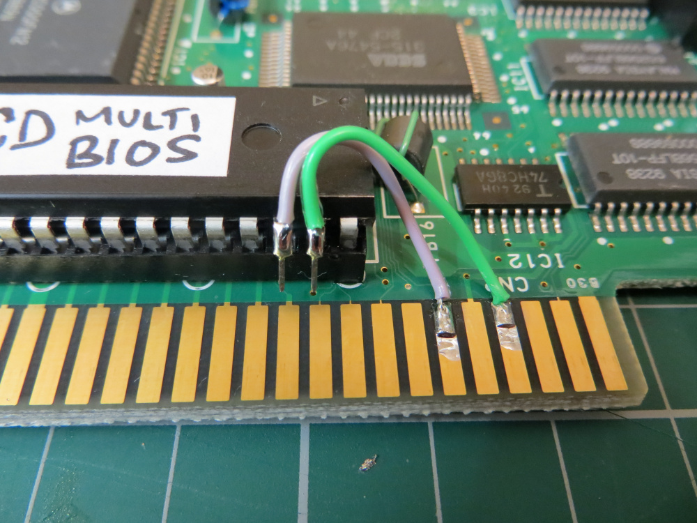
Two wires will need soldering from the expansion port to the two bent out pins.
- Expansion port Pin 4 from the right to MultiBIOS Pin 39
- Expansion port Pin 6 from the right to MultiBIOS Pin 38
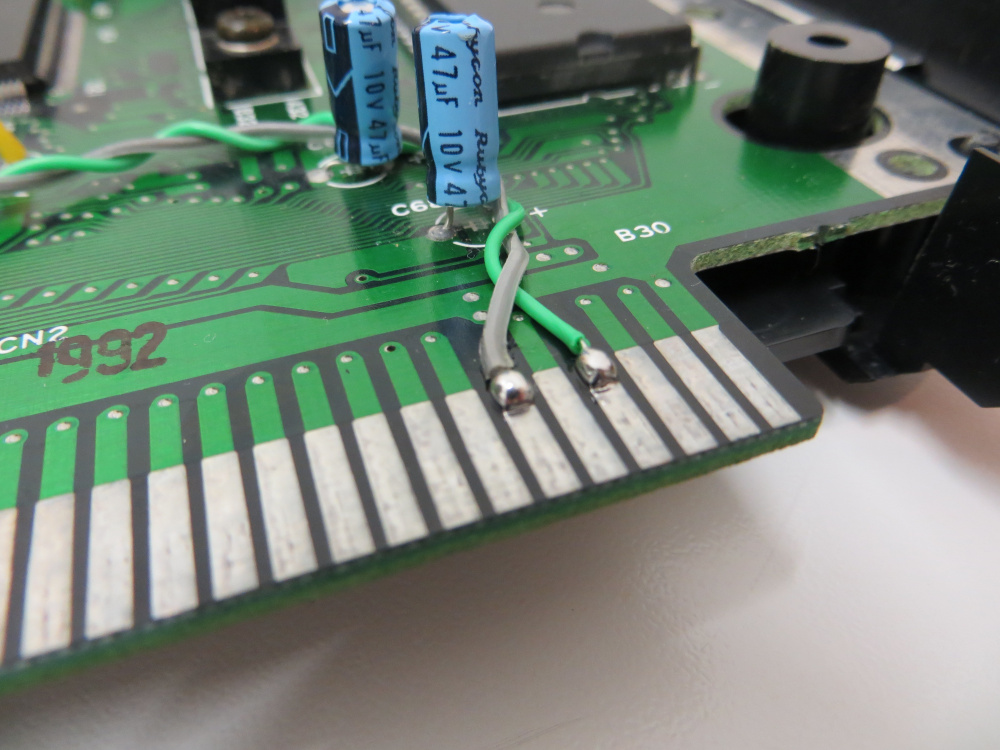
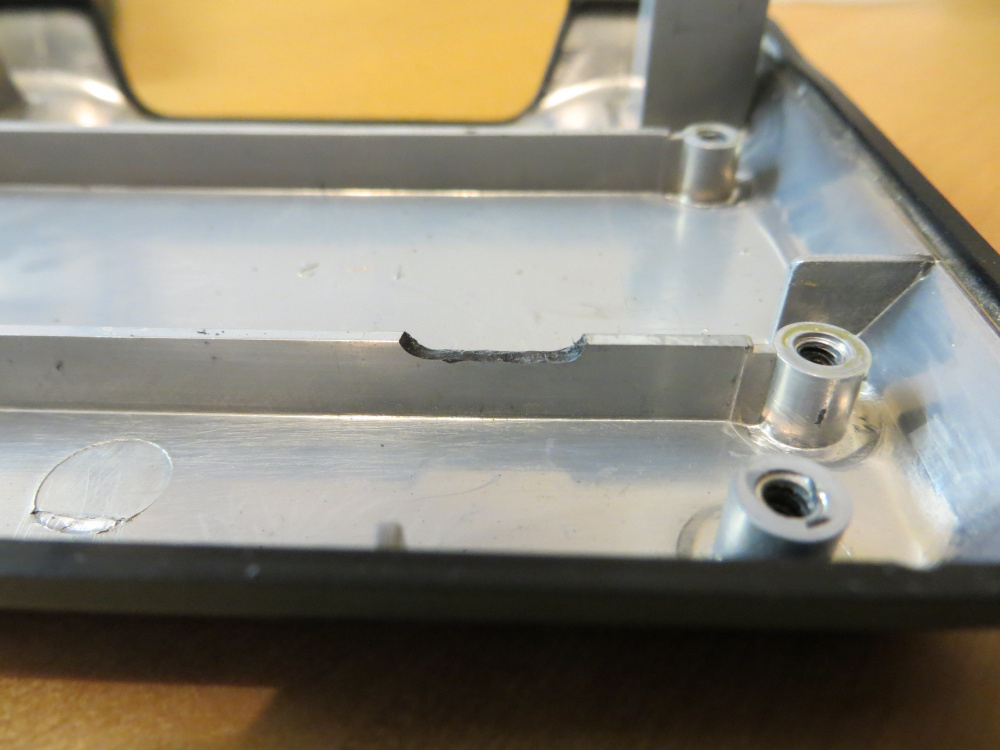
This image shows what happens when you do not use Kapton tape to mask off the port pins. Solder will flow down the pins. You will then have to remove it. Compare this image to the image of the Mega Drive port.
Modding the Mega CD Expansion Port Module
Two wires will need soldering into the module that connects the expansion ports of the Mega Drive and Mega CD.
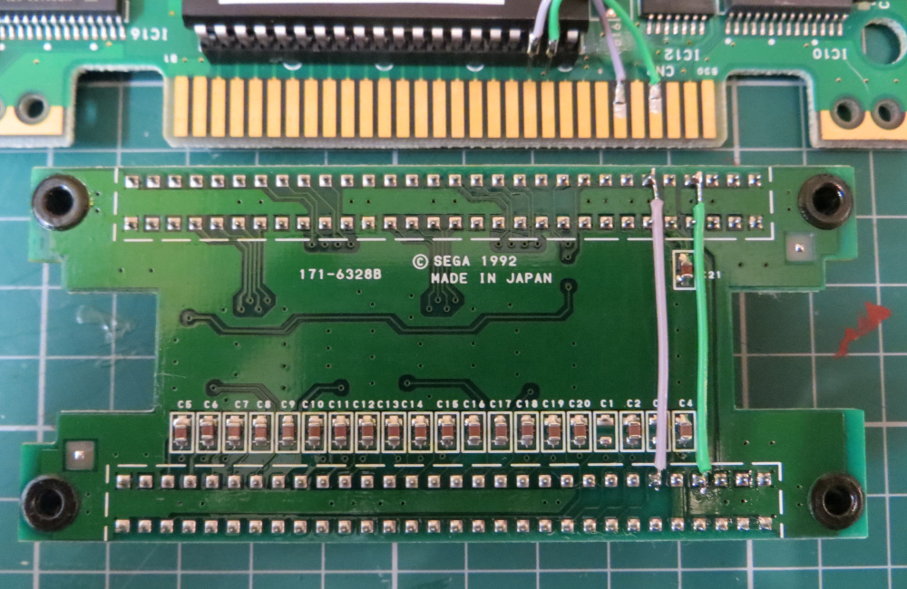
Connect the pins that correspond with the external ports. Pins 4 and 6 from the right side. Also make sure that you are soldering the pins that are for the top side of both the Mega Drive and Mega CD expansion port pins.
These two wires will prevent the board from being able to sit in the case.
Some of the plastic will need removing to allow clearance for the wires.
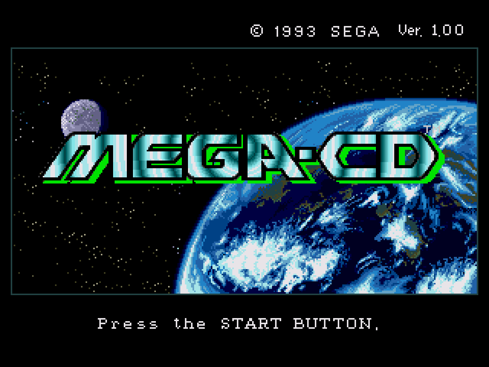
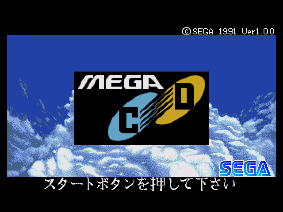
The MultiBIOS BIOS Screens
Setting the Mega Drive to specific regions will load that BIOS for the Mega CD.
Notes
It is not recommended to change the BIOS when the Mega CD is running as this can cause it to crash or glitch. A power cycle is needed when changing BIOS. Unless you are using Borti4938 Mega Drive switchless mod which prevents the BIOS changing until a reset.
However, because these are region free BIOS files, there should be no reason to change the BIOS whilst it is running.
Installing the MultiBIOS with all pins in the socket and not including the additional wiring in the Mega Drive or Mega CD will make the BIOS function as a standard Region Free BIOS.
To Do
- More testing is needed to understand what happens to the Mega CD when attached to a Mega Drive with no region mod.
- When the MultiBIOS is installed with all pins, which BIOS loads? Will this affect the choice of Universal order?
- Mega CD 2 install details.
- Wiring for Mega Drives with black ???graphite/carbon??? plated external port pins.