This guide will show how to install a switchless region mod into a Sega Mega Drive model 2 games console for region free and 60Hz full speed, full screen gaming. This guide is compatible with switchless region PIC codes from D’force3000 (D4S) and Borti4938 and Consoles Unleashed mod kits.
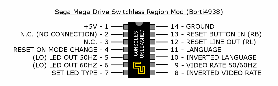
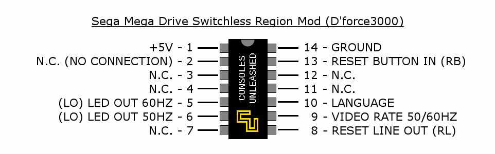
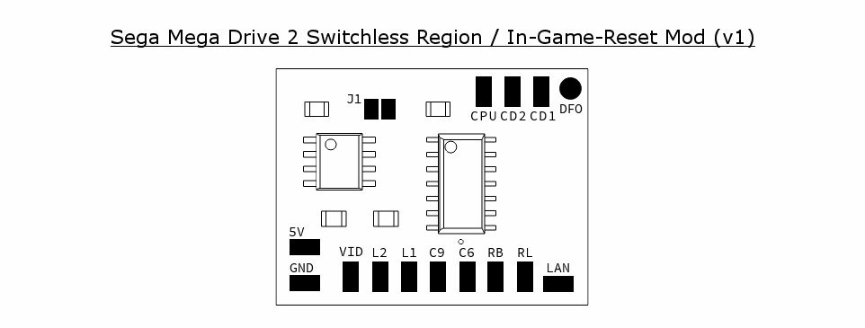
Mod Pinout
Solder Maps
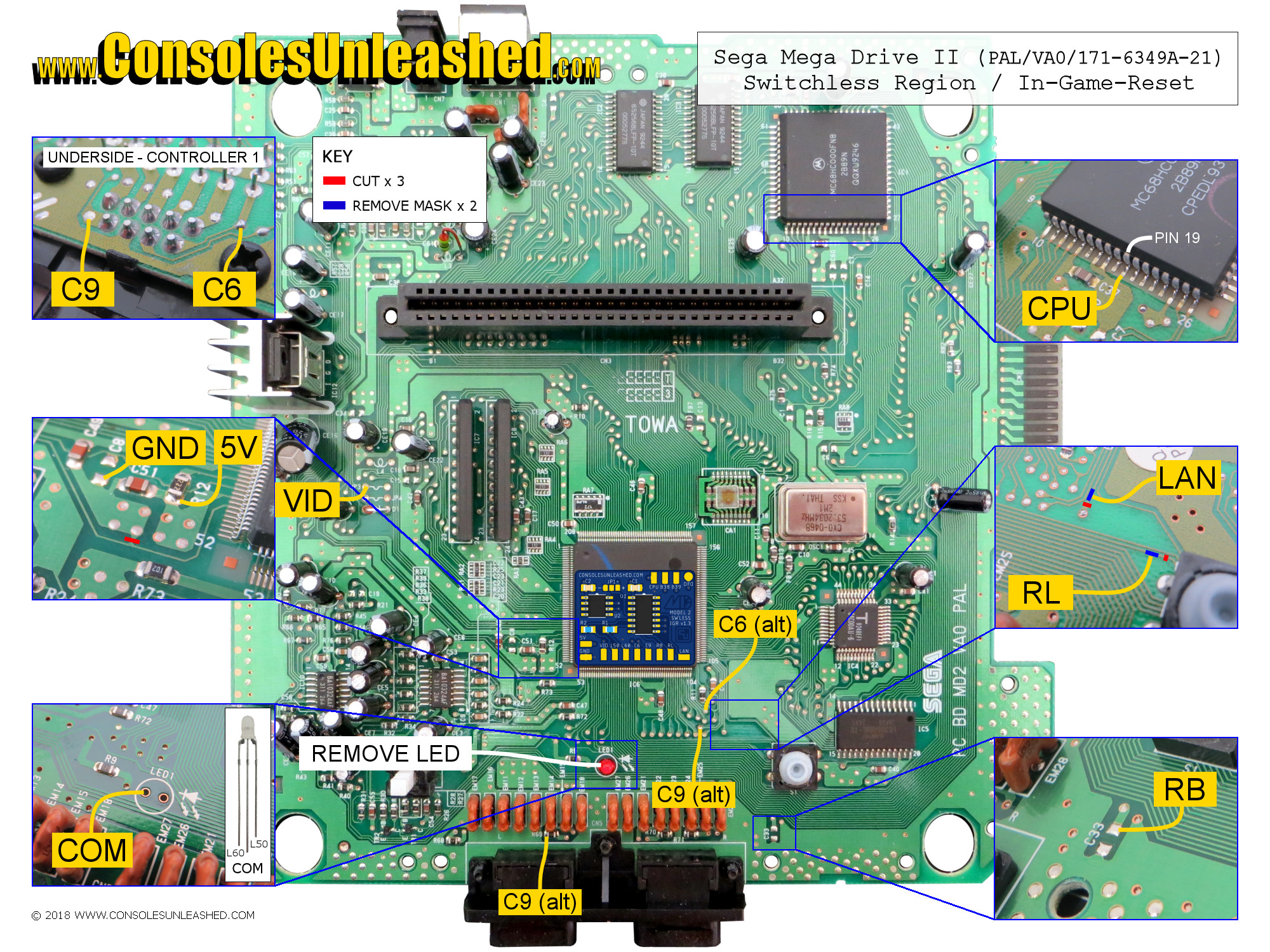
Sega Mega Drive 2 – VA0 / PAL / 171-6349A-21
Sega Mega Drive 2 – VA1 / PAL / 171-6534A-21
Will be added soon.
Sega Genesis 2 – VA1 / NTSC-U / 171-6534A-10
Will be added soon.
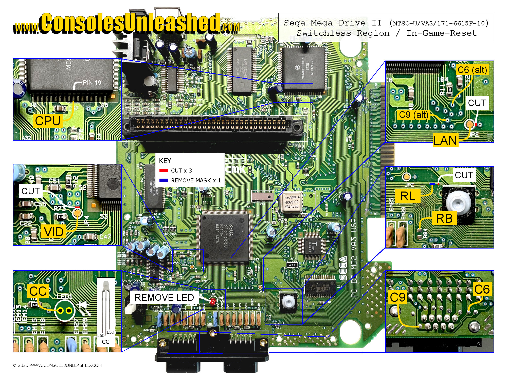
Sega Genesis 2 – VA3 / NTSC-U / 171-6615F-10
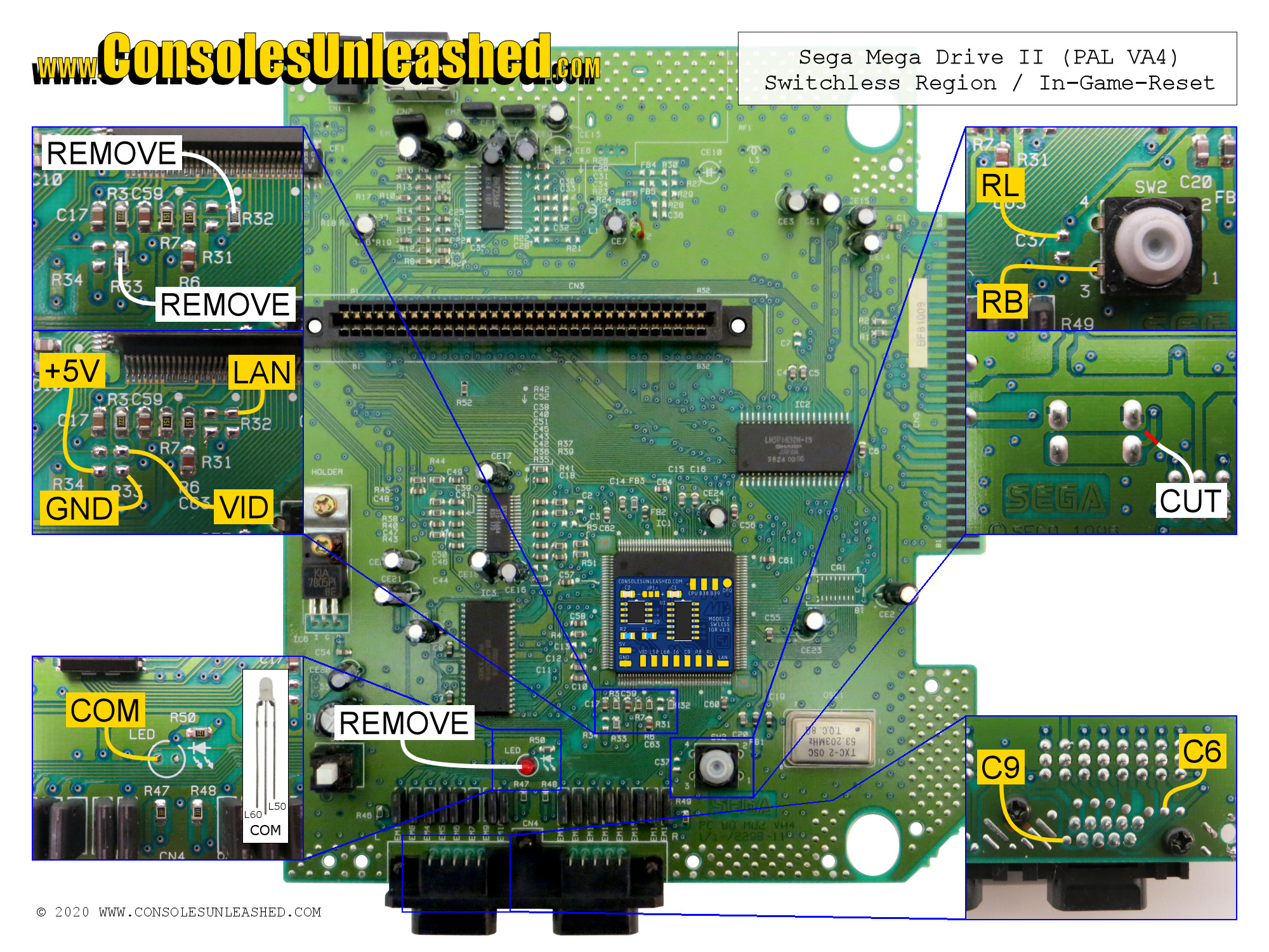
Sega Mega Drive 2 – VA4 / PAL / 171-72298-11
CPU Halt
- CPU Pin 19
When this is connected the game will pause when START+A+B+C is held long enough to start cycling through the console’s regions. Only connect this if you want the game to pause when cycling through the regions.
VA4 Halt point is unknown at this time, but will be added later.
LED
There are two types of LED solder points on the model 2 Mega Drive. Some are through hole plated with a solder pad on the top and bottom layers. The other type is not through plated and only has a pad on the bottom of the board. When pushing the LED through this second type there is a great risk that the pad on the underside can lift and tear off. Be careful when threading the LED.
The LED will need soldering into the original ground hole on the Mega Drive mainboard labelled COM or CC. For this reason a common cathode LED is used for Mega Drive 2 region modding. The common LED pin will need bending in a specific way in order for the common pin to line up and centralise the LED to the location of the original LED, this requires two bends. One straightening the pin outwards and a second bending the pin downwards. The two outer pins will need bending at right angles opposite to the common pin and wiring to the LED OUT pins on the modchip.
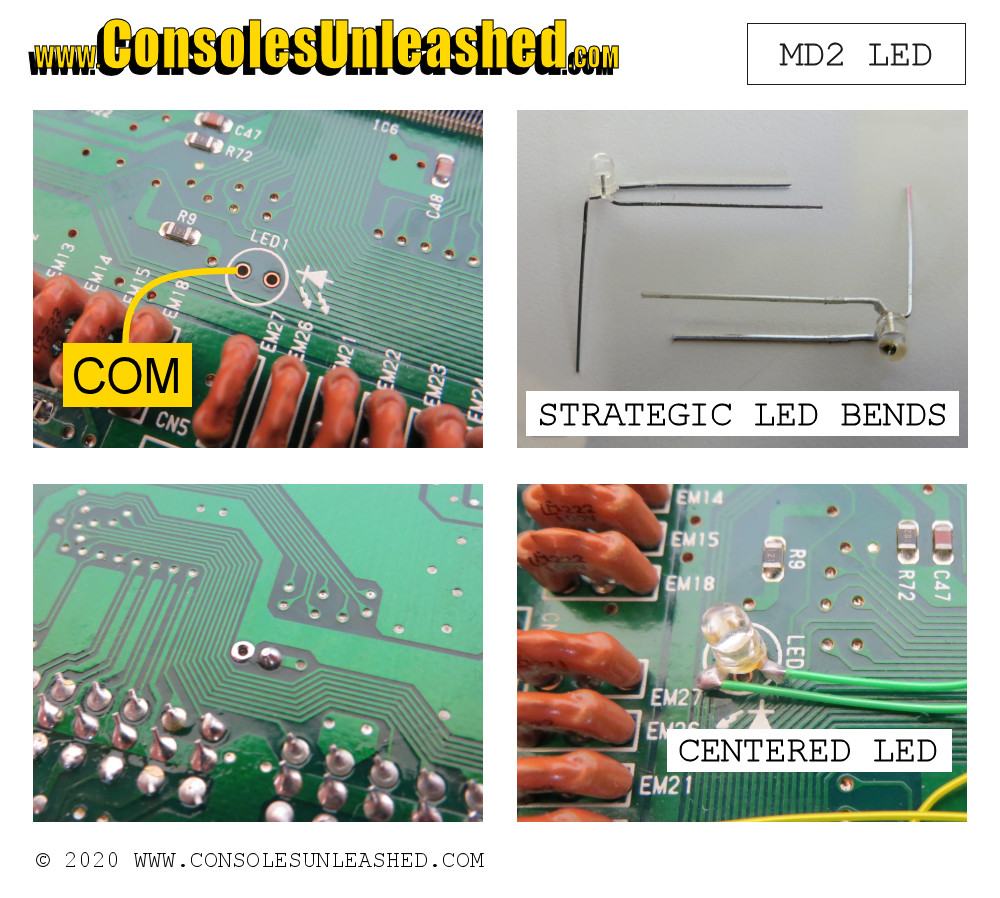
The LED or the wires will not move once in place so there is no need to add heatshrink tube to the LED pins for strain relief.
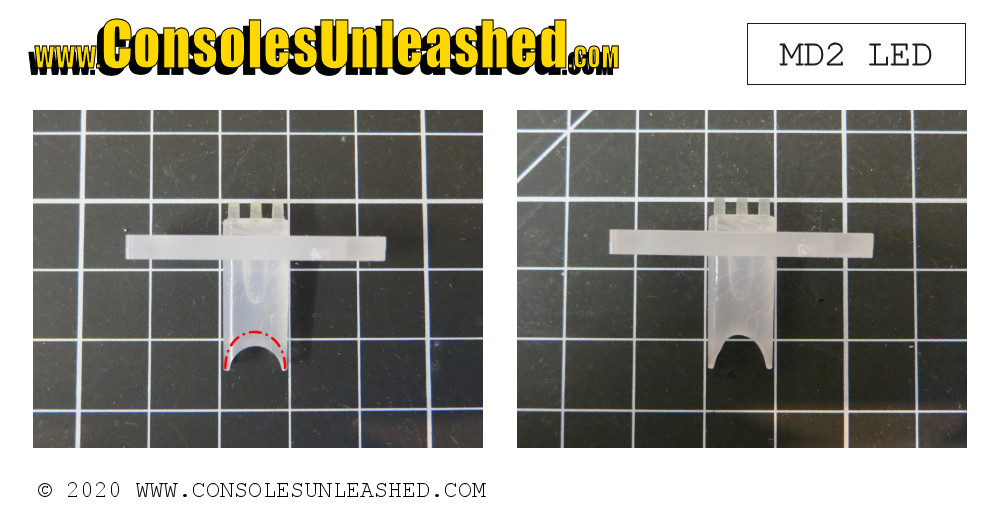
Diffuser
Depending how the LED pin bends were made, the new LED might not fit below the diffuser. In this case some material will need removing from the diffuser. A rotary tool is best for this task. In order to avoid this, make sure the LED pin bends are tight and flush to the LED bulb.
Controller C6 & C9
- C6 to Controller Port Pin 6 which detects when A+B is pressed.
- C9 to Controller Port Pin 9 which detects when C+Start is pressed.
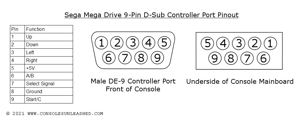
To get the wires to the bottom of the board for soldering these points you can go through the controller connector case. Threading the wire from the bottom of the board to the top through the connector is the easiest method for this.
Alternative Controller Points
Alternatively you can scrape solder mask off two vias on the top of the board for soldering the wires. This requires a permanent modification to the board and is very fine soldering which some might find difficult.
Power and AV Socket Fix
Whilst the console is open it is a good idea to check if the solder connections on the bottom of the board for the sockets are intact. More often than not, they are broken and need resoldering.
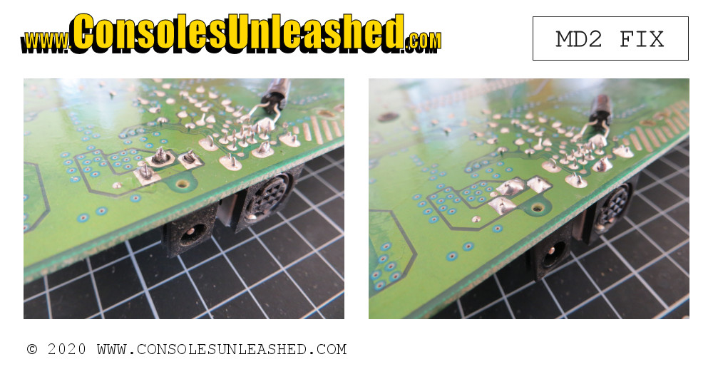
If broken, apply some new solder and flow until the connections become whole again.
Notes
Still need to find and add the CPU Halt location for VA4.