This guide will show you how to get RGB video out of the Sega Master System model 2. It will be compatible with all stock Master System or Mega Drive 2 SCART cables depending on the output connector used. The guide covers both a passive RGB mod which will take the video from the console’s native RGB Encoder, and an active RGB bypass mod which will take the video from the console’s native Video Display Processor and “bypass” the console’s RGB Encoder.
Solder Maps
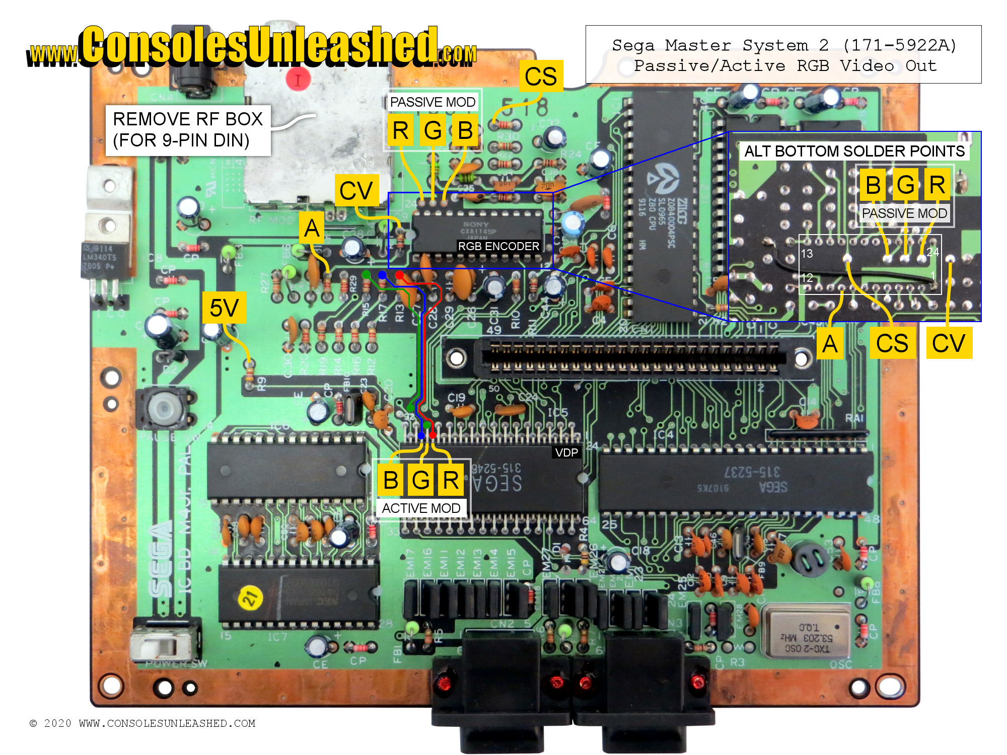
Sega Master System 2 – PAL / IC BD M4 Jr / 171-5922A
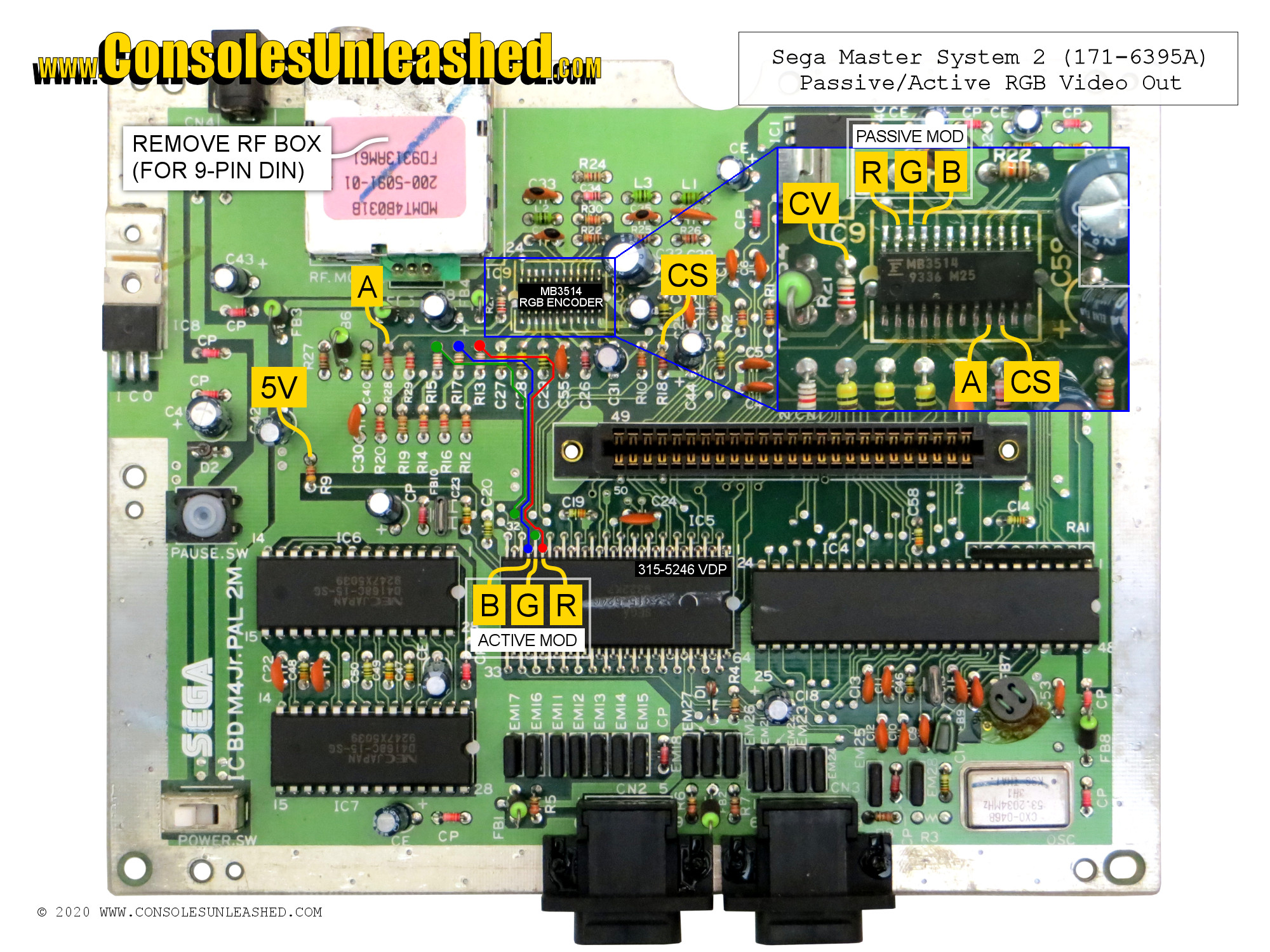
Sega Master System 2 – PAL / IC BD M4 Jr.PAL 2M / 171-6395A
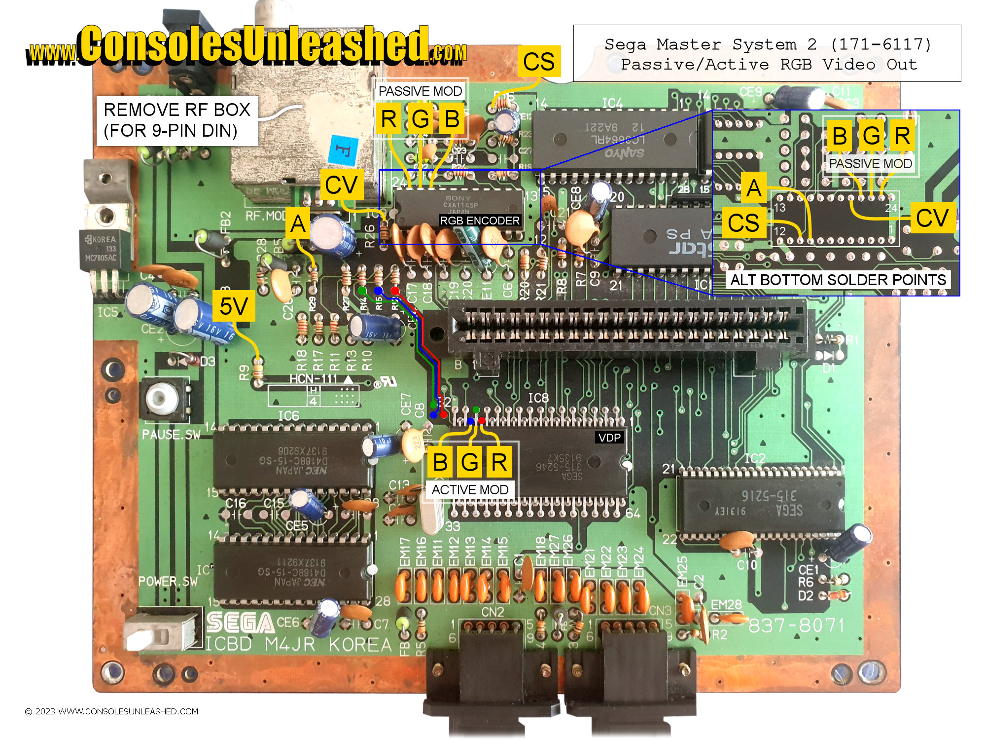
Samsung Gamboy 2 – NTSC / ICBD M4JR KOREA / 837-8071 / 171-6117
Schematics
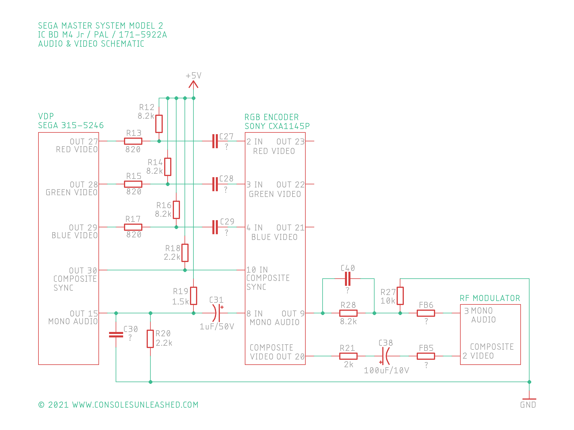
Sega Master System 2 – PAL / IC BD M4 Jr / 171-5922A
The schematic for SMS2 – PAL / IC BD M4 Jr.PAL M2 / 171-6395A uses the same part designations.
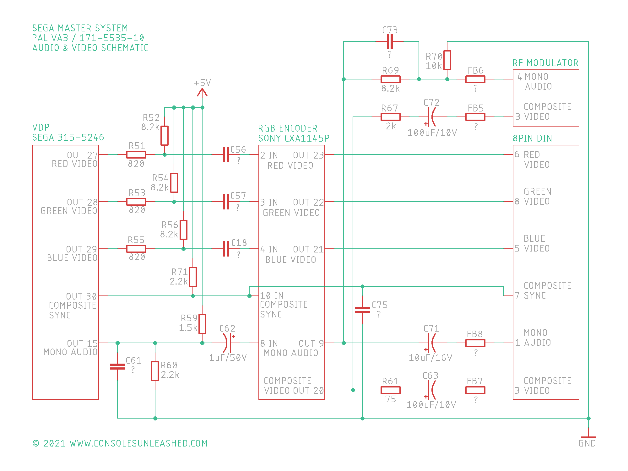
Sega Master System 1 – PAL / VA3 / 171-5535-10
Missing Components
When comparing the Audio/Video schematics for Master System 1 and Master System 2 the following components are missing.
- 10uf/16v electrolytic capacitor followed by a ferrite bead on the audio line out from the RGB Encoder.
- 75ohm resistor followed by a 100uf/10v electrolytic capacitor followed by a ferrite bead on the composite video line.
- The Red, Green & Blue video signals are direct to the AV connector from the RGB Encoder.
- 8pin DIN
Mod Pinouts
The mod is concerned with two ICs inside the Master System. The Video Display Processor and the RGB Encoder.
For a passive RGB mod, take the RGB signals from the RGB Encoder.
For an active RGB bypass mod, take the RGB signals from the Video Display Processor.
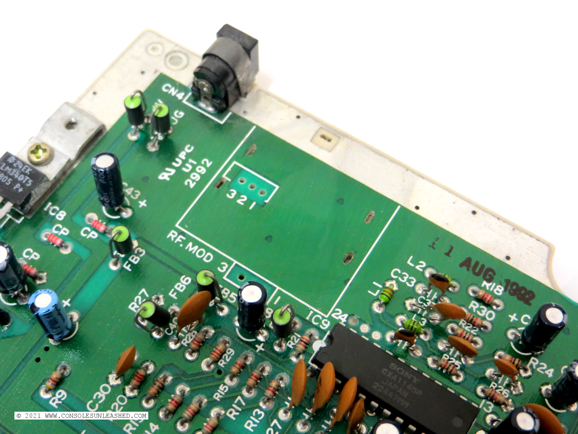
Sony CXA1145P RGB Encoder (171-5922A revision consoles)
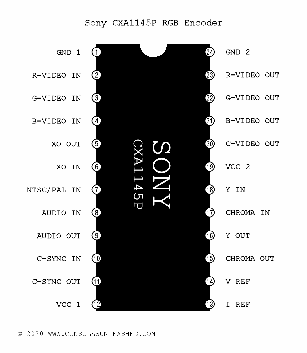
- Pin 23 for Red Video (Passive Mods)
- Pin 22 for Green Video (Passive Mods)
- Pin 21 for Blue Video (Passive Mods)
- Pin 20 for Composite Video
- Pin 10 for Composite Sync (Yes, from the C-SYNC IN pin). (Take signal from the 2.2K pull-up resistor.)
- Pin 9 for Mono Audio
Fujitsu MB3514 RGB Encoder (171-6395A revision consoles)
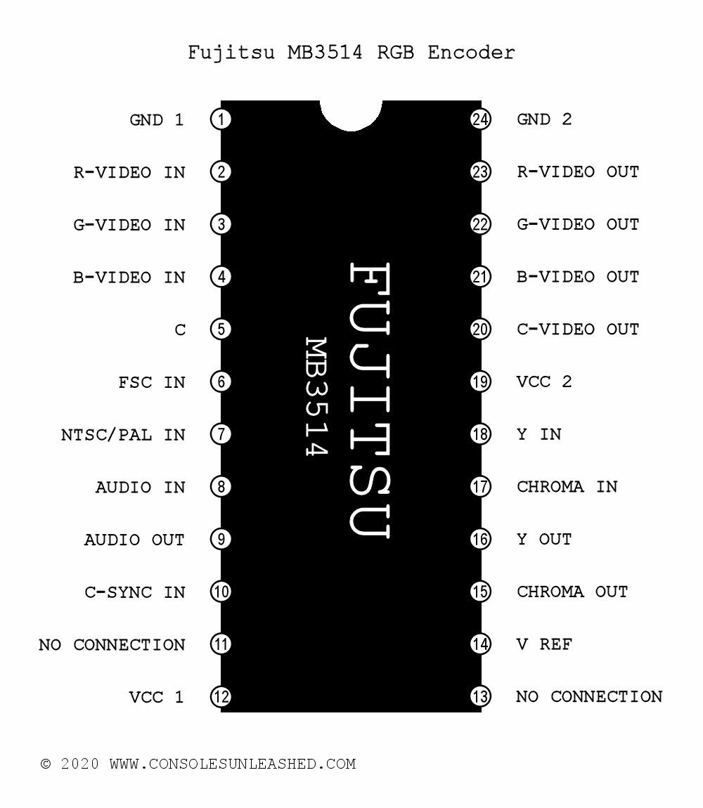
- Pin 23 for Red Video (Passive Mods)
- Pin 22 for Green Video (Passive Mods)
- Pin 21 for Blue Video (Passive Mods)
- Pin 20 for Composite Video
- Pin 10 for Composite Sync (Yes, from the C-SYNC IN pin). (Take the signal from the 2.2K pull-up resistor.)
- Pin 9 for Mono Audio
SEGA 315-5246 Video Display Processor
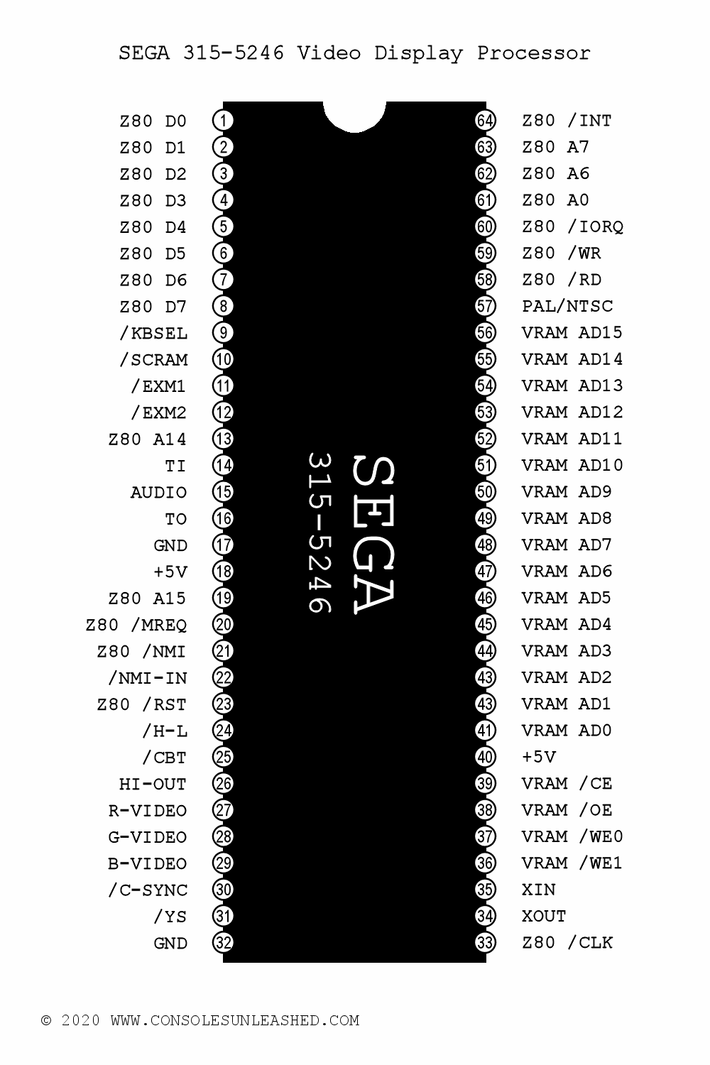
- Pin 27 for Red Video (Active Mods)
- Pin 28 for Green Video (Active Mods)
- Pin 29 for Blue Video (Active Mods)
- Pin 30 for Composite Sync
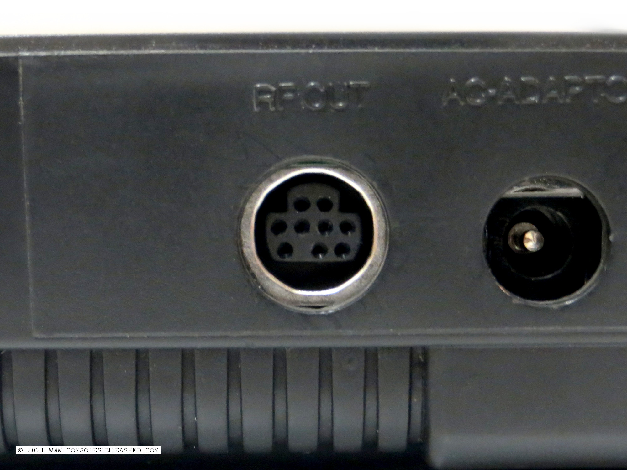
Output Audio/Video Connector
There is a choice of two connectors to make the RGB mod backwards compatible with Master System 1 or Mega Drive 2 cables.
9-Pin Mini DIN (Through hole/Surface mount)
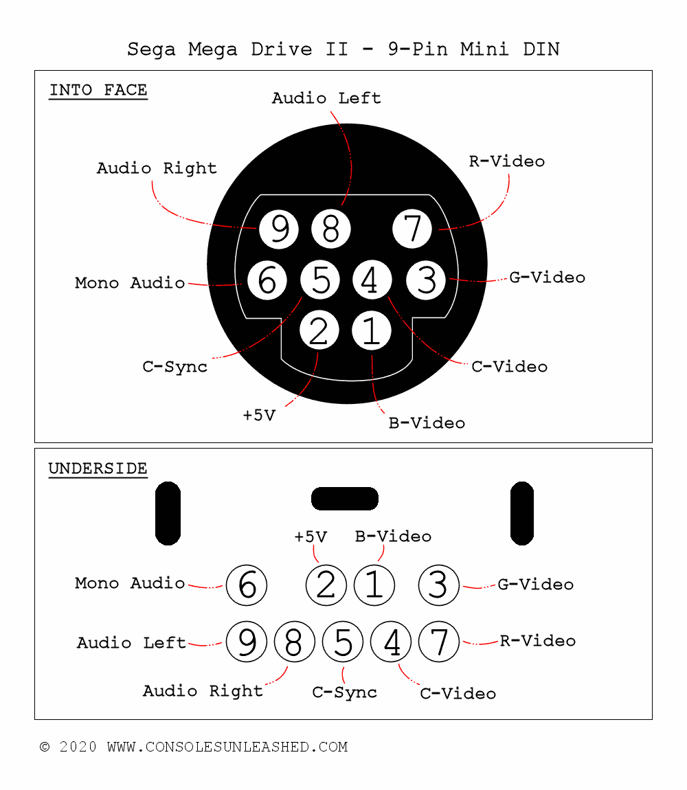
The use of this connector will require the removal of the RF box.
262 Degree “U-shape” 8-Pin DIN (Panel Mount version)
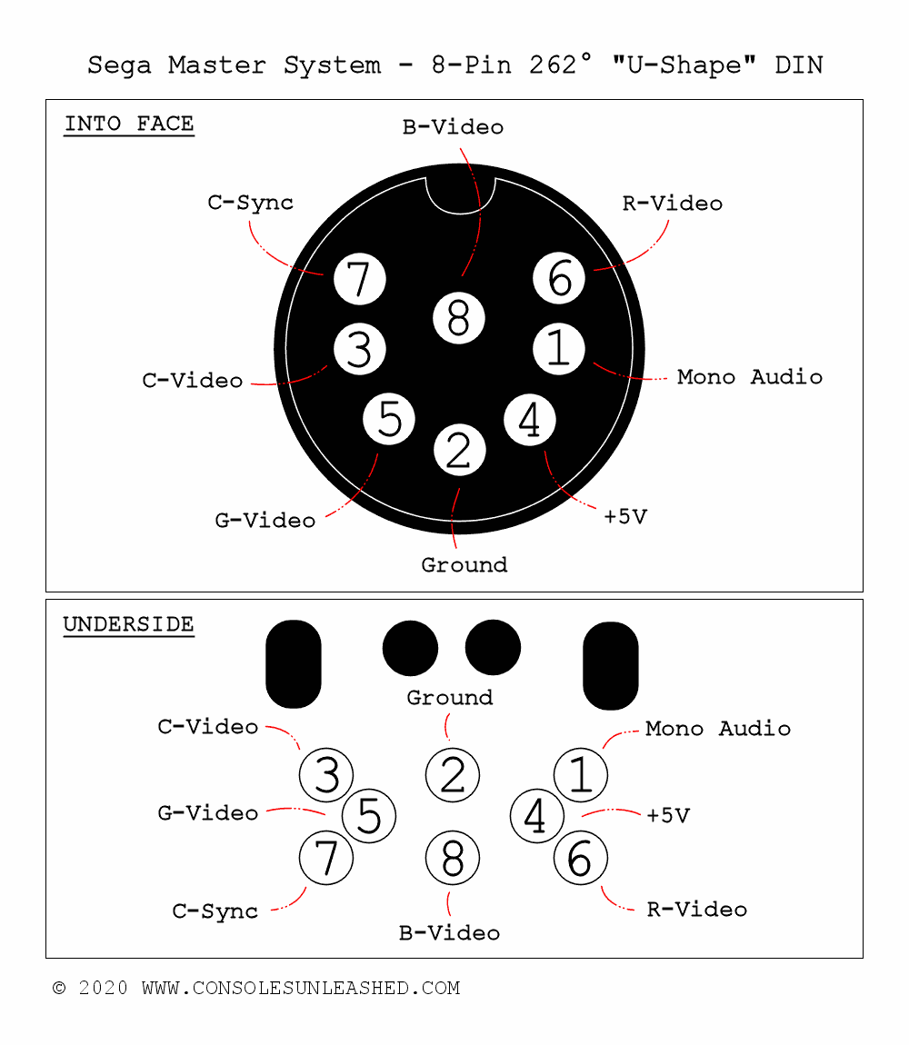
The use of this connector will require a hole cutting in the Master System case. Alternatively the RF box can be removed and the hole made larger.
SCART Cable Components
Details and schematic coming very soon
Consoles Unleashed RGB Mod Kits – Step-by-Step Install Guide
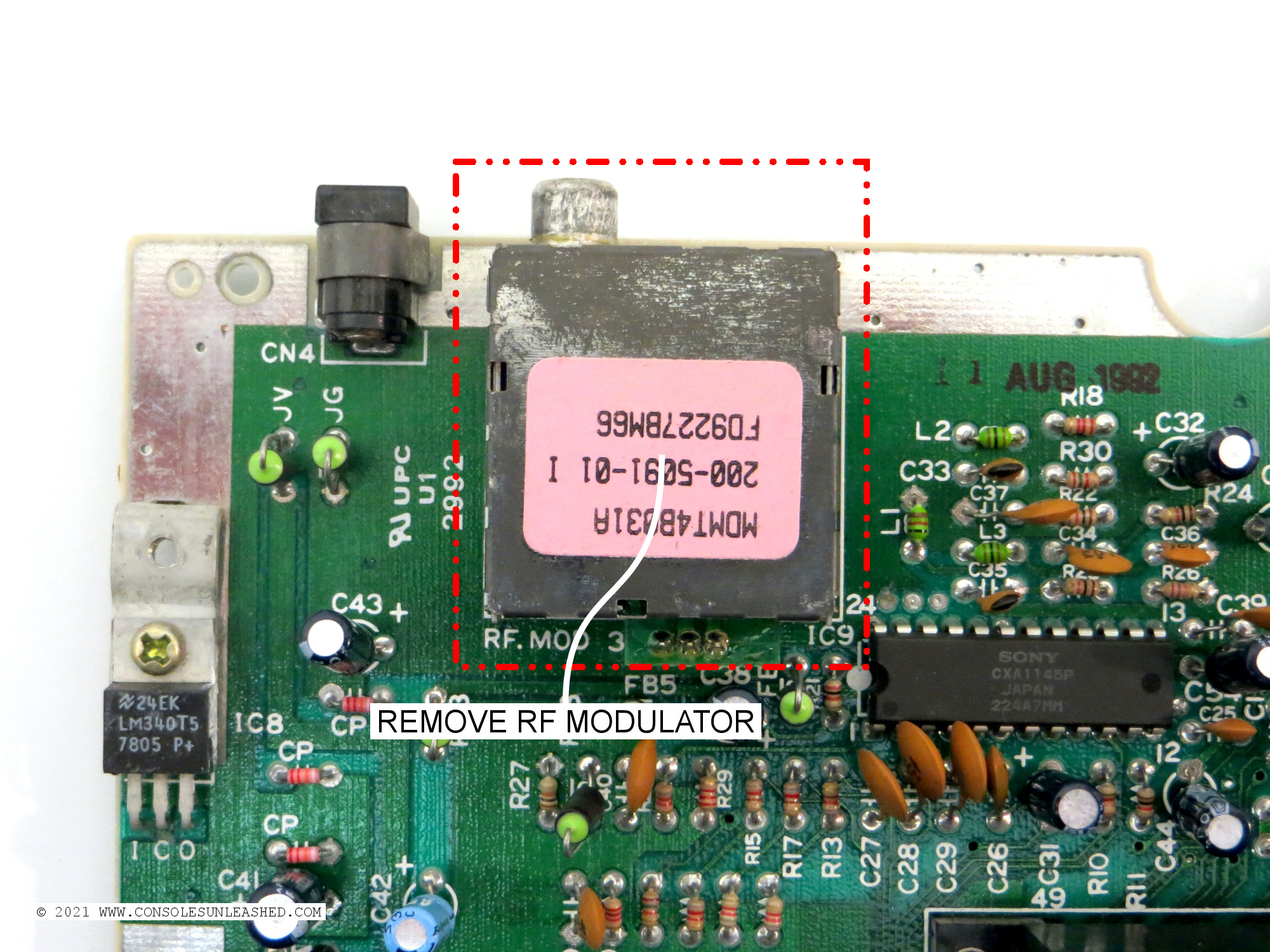
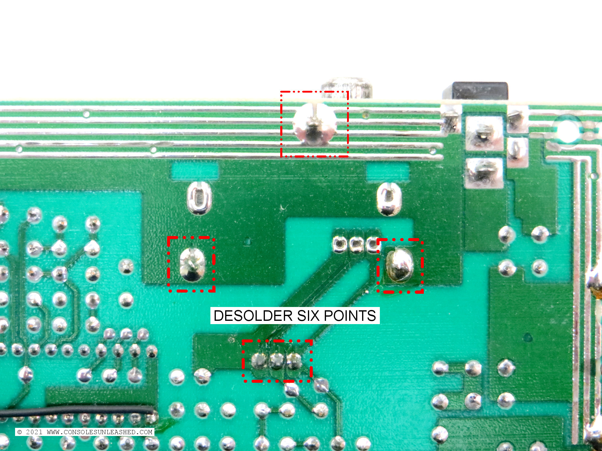
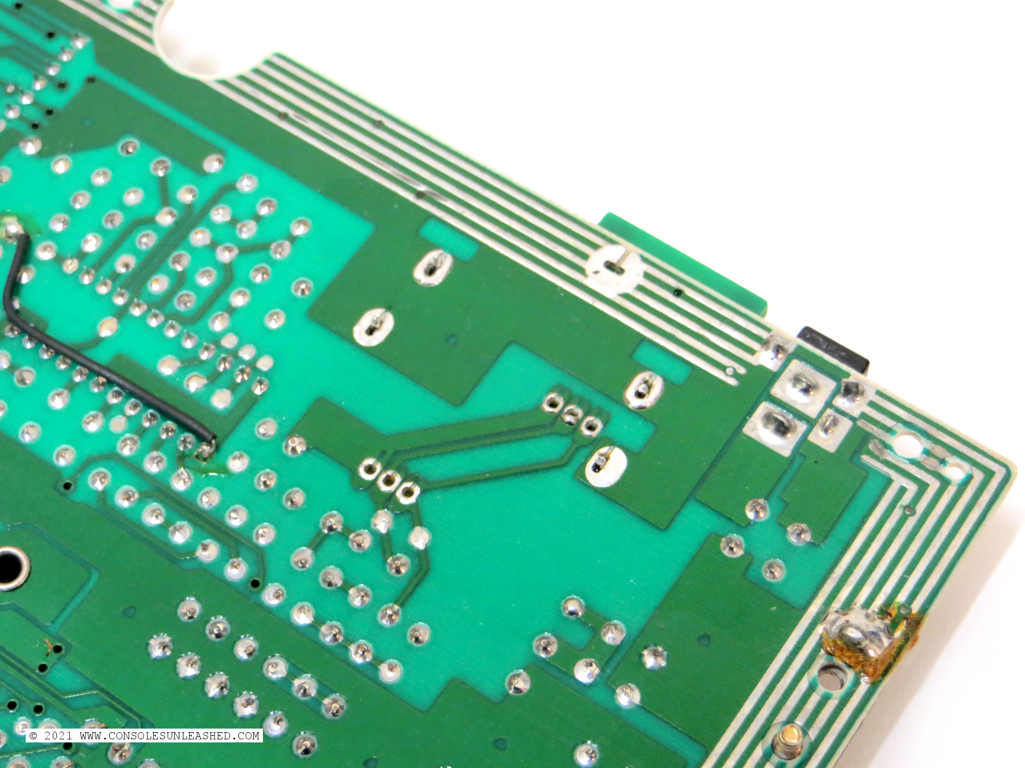
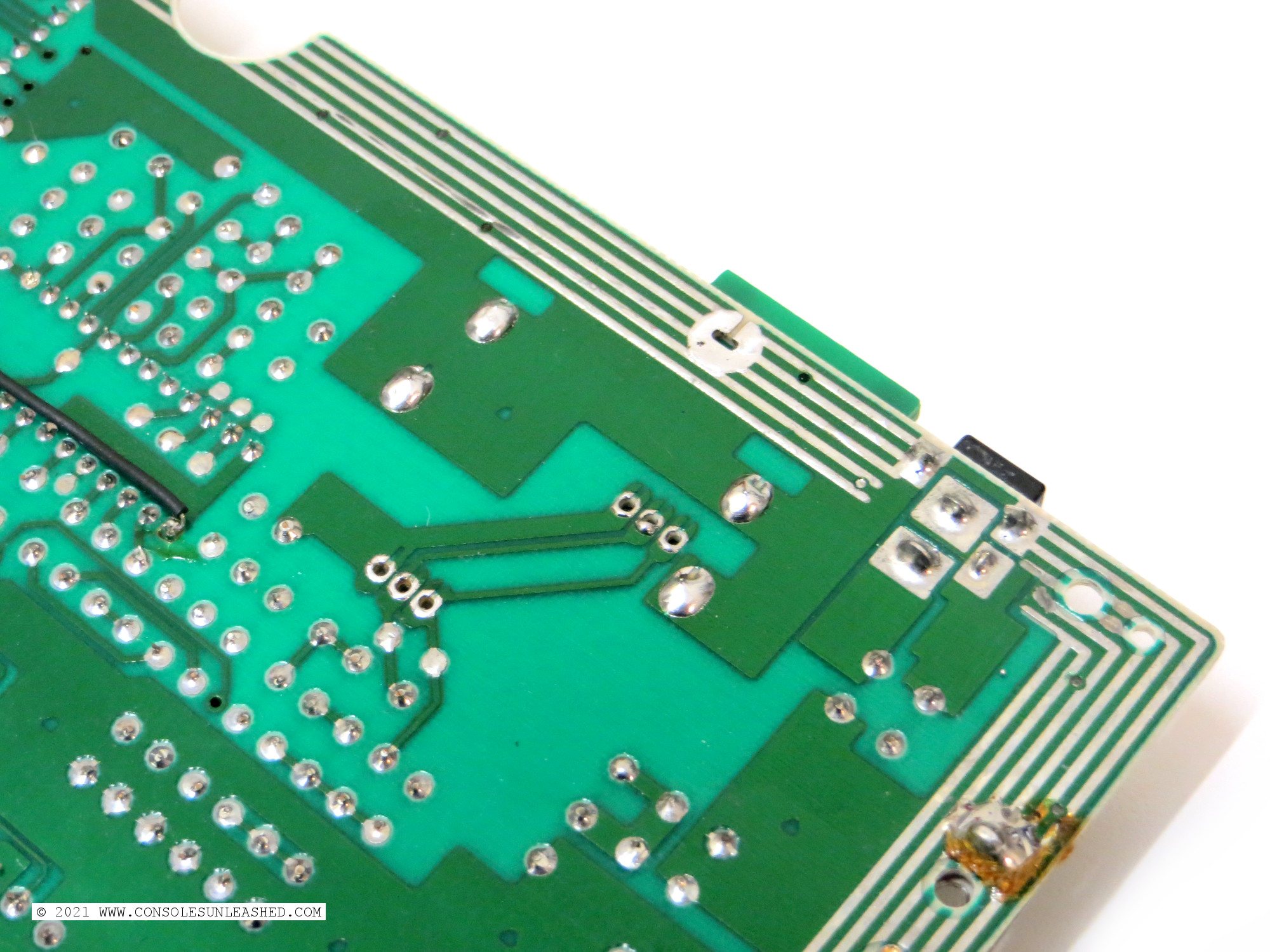
Remove RF Modulator
This can be done with a standard solder pump and a high soldering iron temperature.
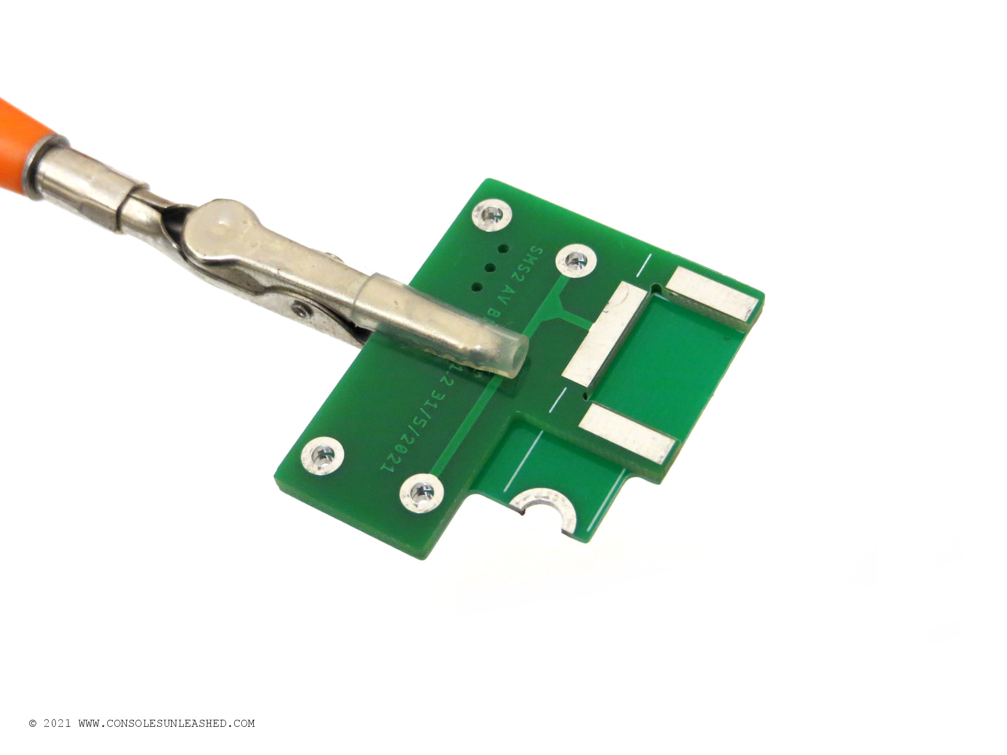
Make the Mount/Brace Assembly
Start by soldering the mount and brace together with the included turrets.
This can be done by hand, in a horizontal vice, or a pair of helping hands as shown here. Make sure the mount and brace are perfectly aligned and insert the turrets with the sharp point down then solder them in place. If the turrets are not straight, reheat whilst straightening.
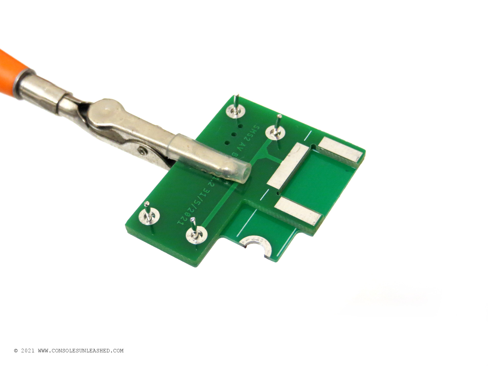
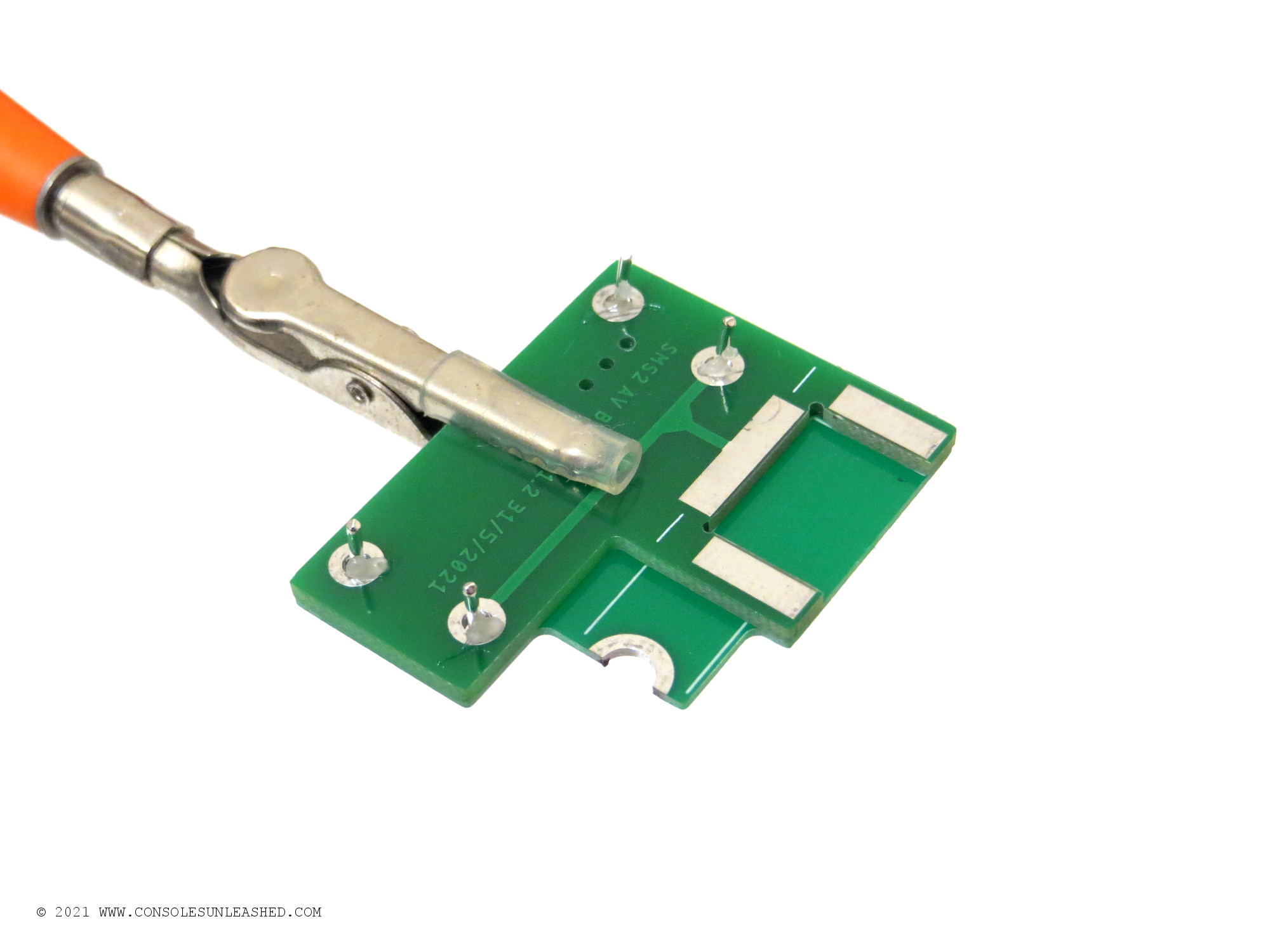
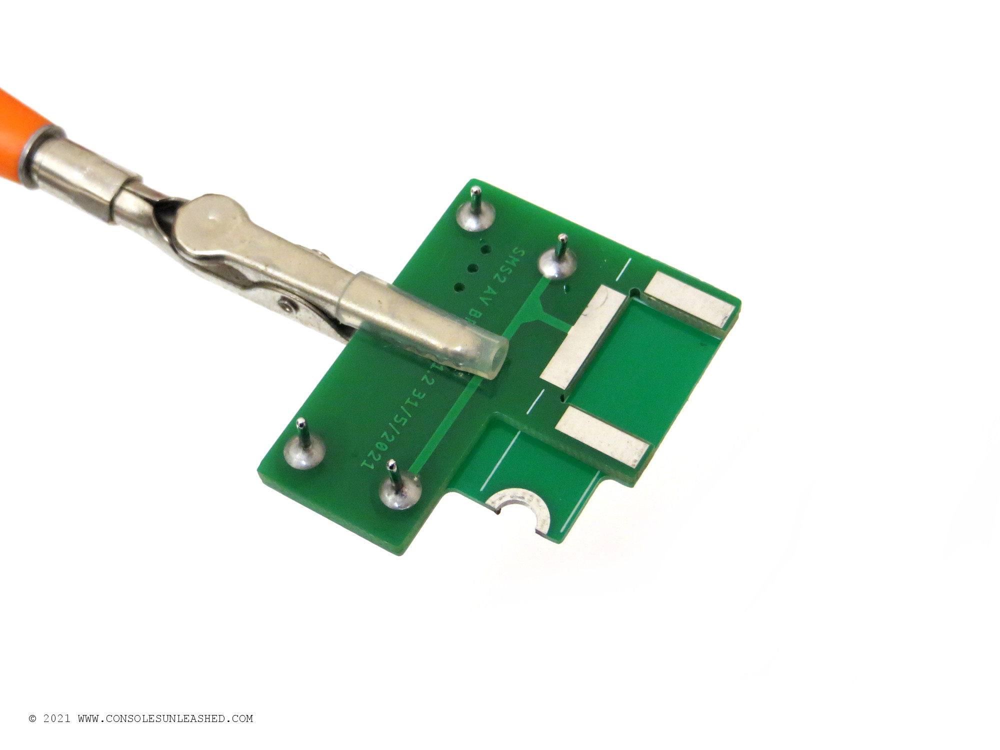
If doing it by hand, firmly grip the PCBs together making sure they are aligned. Then add plenty of flux to the turret holes. Solder the turrets in place by pre-loading the soldering iron tip with solder and applying it to the holes. The flux in the holes will allow the solder to flow and make a solid connection.
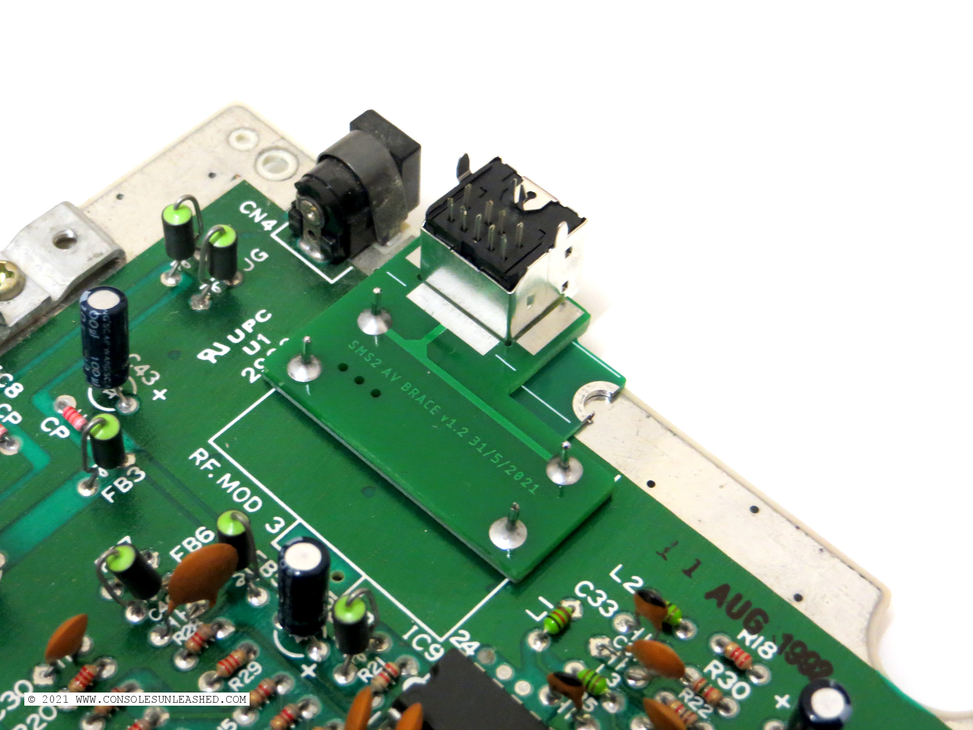
Attaching the Mount Brace Assembly
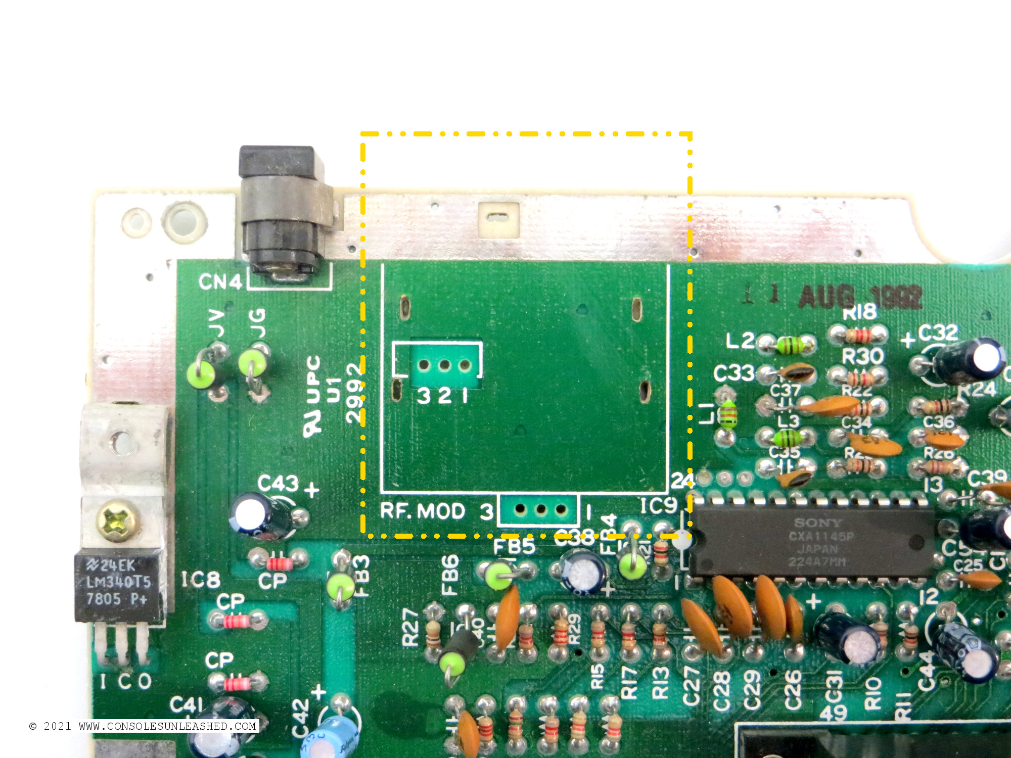
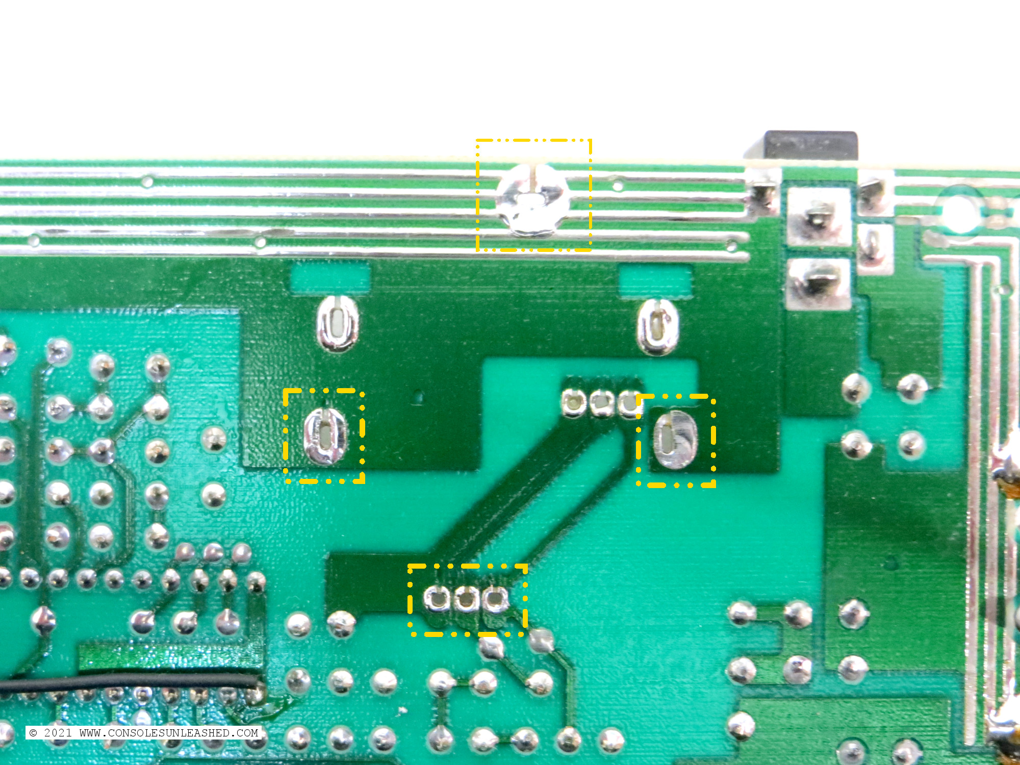
Once the assembly is constructed it can be placed into the holes left behind when removing the RF modulator.
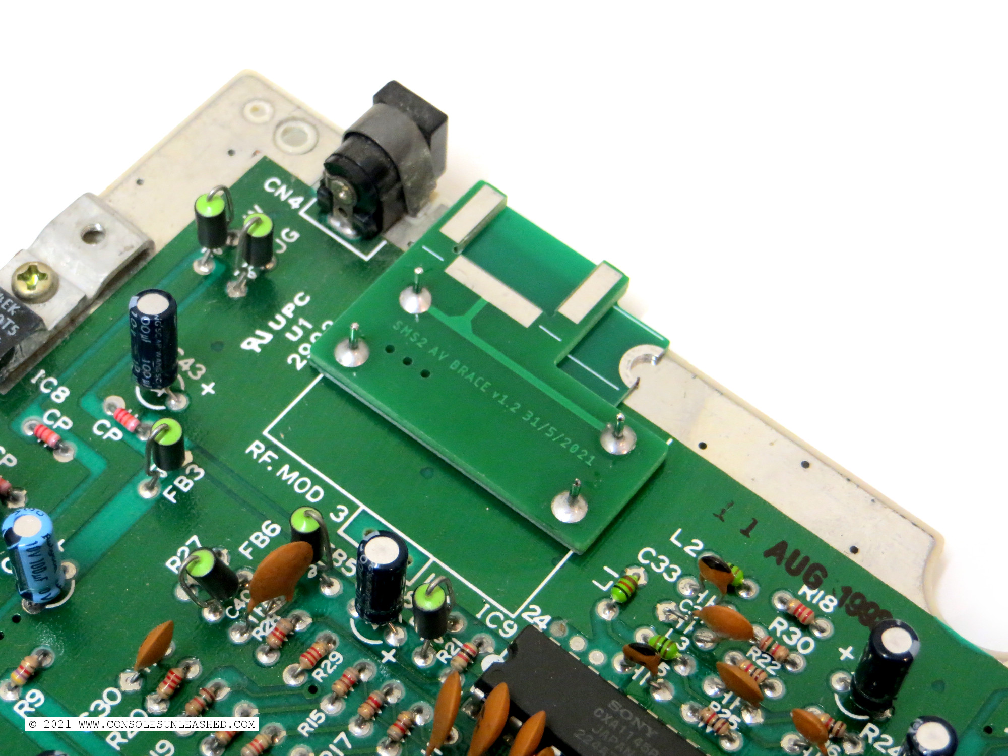
Turn over the Master System mainboard and lightly solder in the turrets. Only do it lightly so the position can be easily adjusted later if needed. If confident it is aligned perfectly, it can be soldered in fully.
Adding the 9-Pin Mini DIN
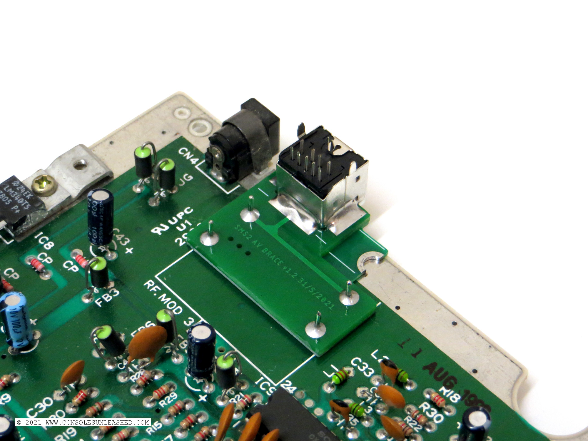
Add lots of solder to the three pads that surround where the connector will be placed.
Place the connector into position. Make sure the connector is sitting flat.
Using a high soldering iron temperature, reheat the solder and simultaneously heat the side of the connector. The solder should eventually adhere to the connector. Do this for all three sides.
Once the connector is secure the position of the entire assembly can be adjusted to align correctly with the hole left by the RF modulator. Fully solder the four posts once the position is good.
Attaching the Hood & Wiring
Add the Hood PCB and then wire up the connections shown on the solder map for the type of RGB mod used.
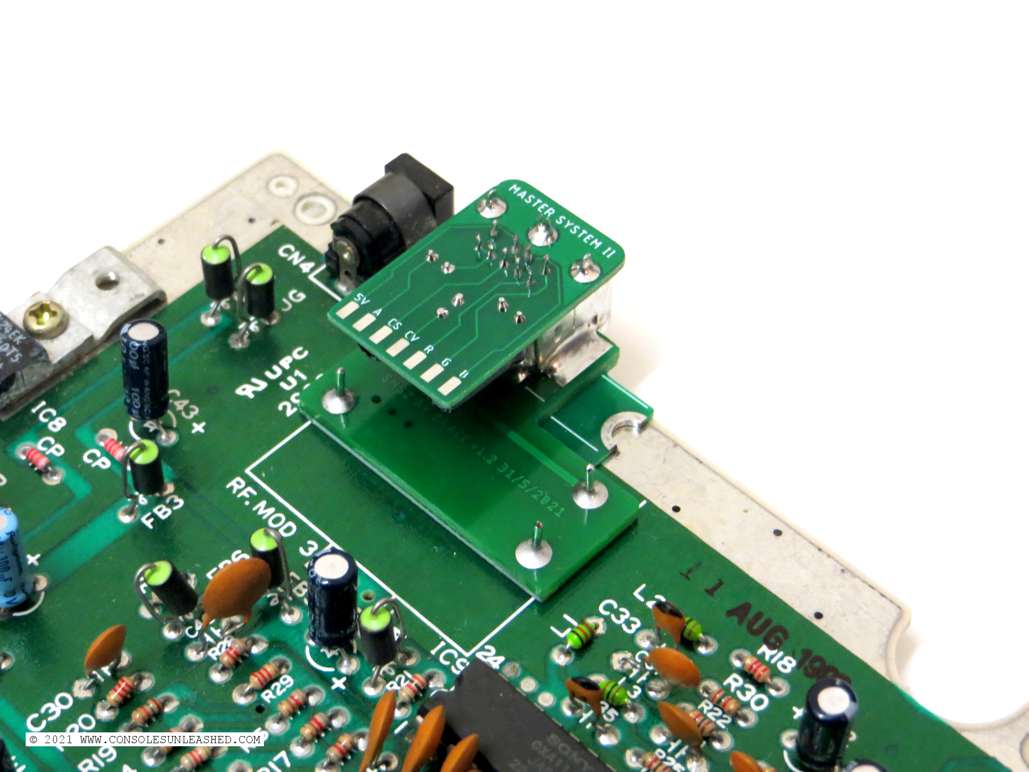
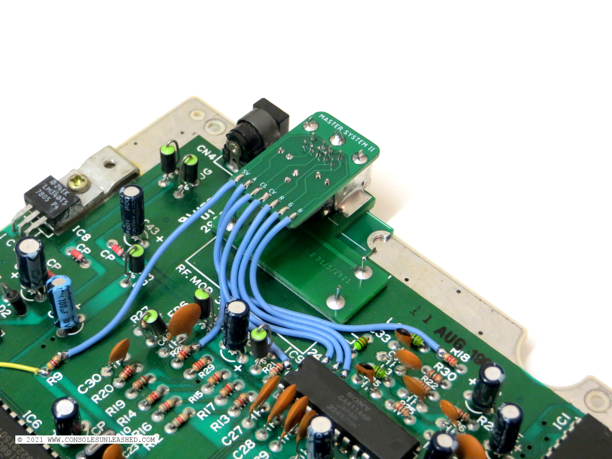
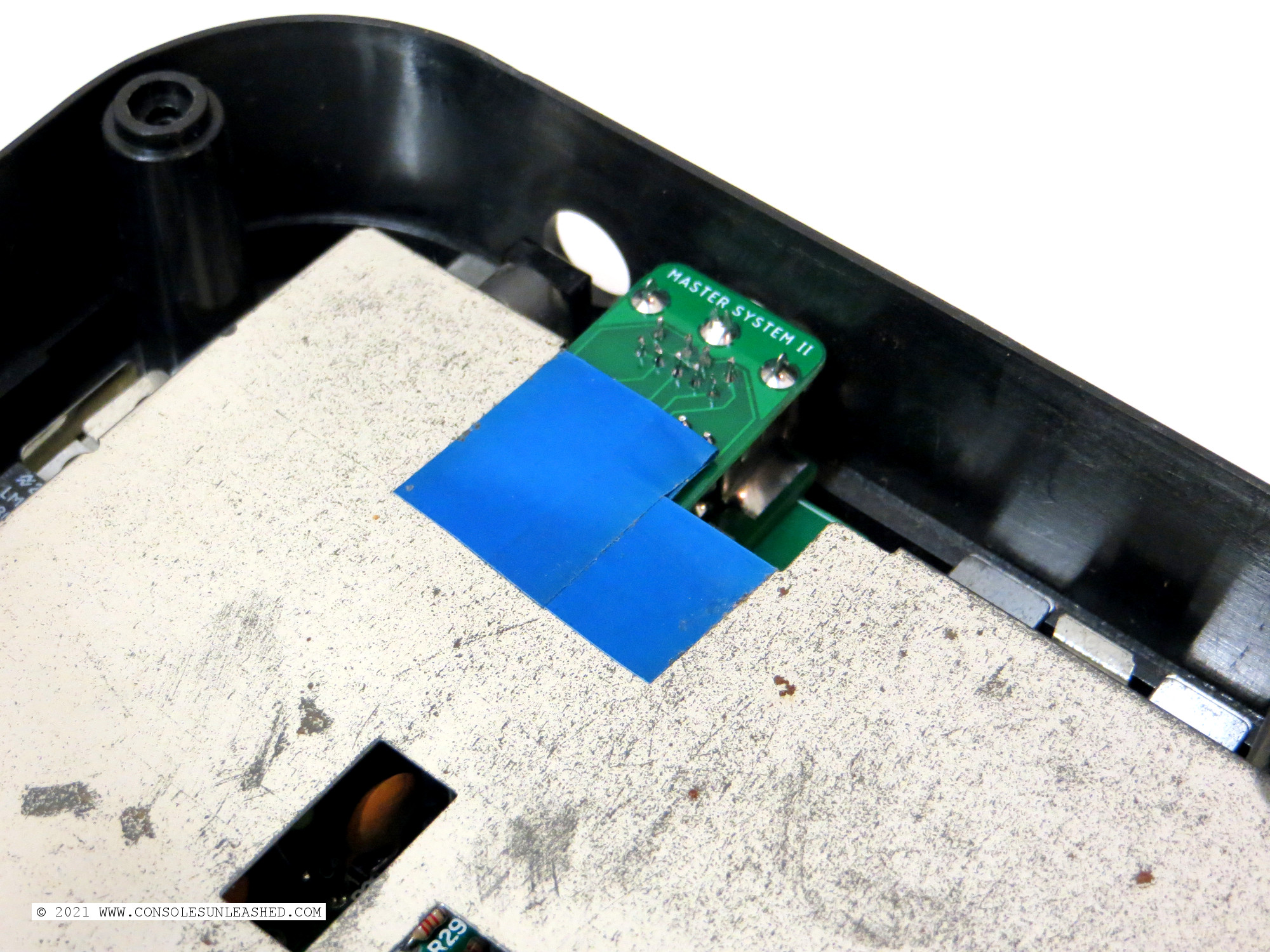
A square might need cutting from the RF shield directly above where the Hood PCB is located or some electrical tape can be adhered to the RF shield to prevent the RF shield shorting with the Hood PCB solder connections and components.
Plug In and Test
Plug in a Mega Drive 2 RGB SCART cable and be astonished at the glorious RGB video signal displayed on the telescreen.